
Electric power cabinet emergency protection device with fireproof and flame-retardant functions
A fire retardant, protective device technology, applied in the substation/distribution device enclosure, substation/switchgear cooling/ventilation, substation/switch layout details, etc., can solve problems such as fire spread, safety hazards, etc., to improve efficiency , reduce safety hazards and improve the effect of fire extinguishing
Patent Information
- Authority / Receiving Office
- CN · China
- Patent Type
- Applications(China)
- Current Assignee / Owner
- Publication Date
- 2022-06-07
Smart Images
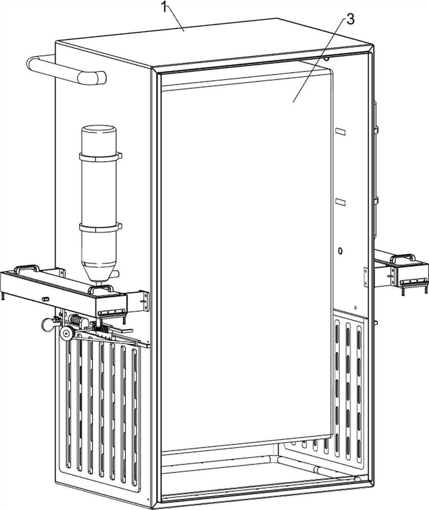
Figure 1 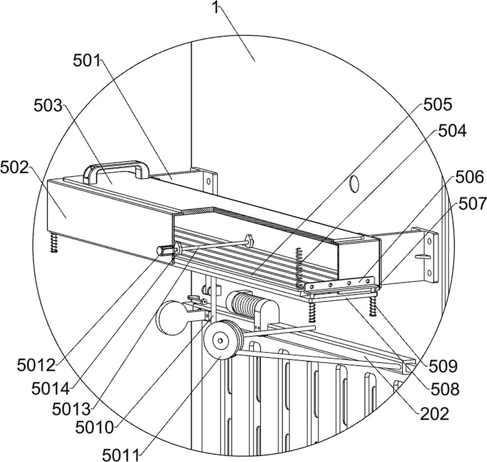
Figure 2 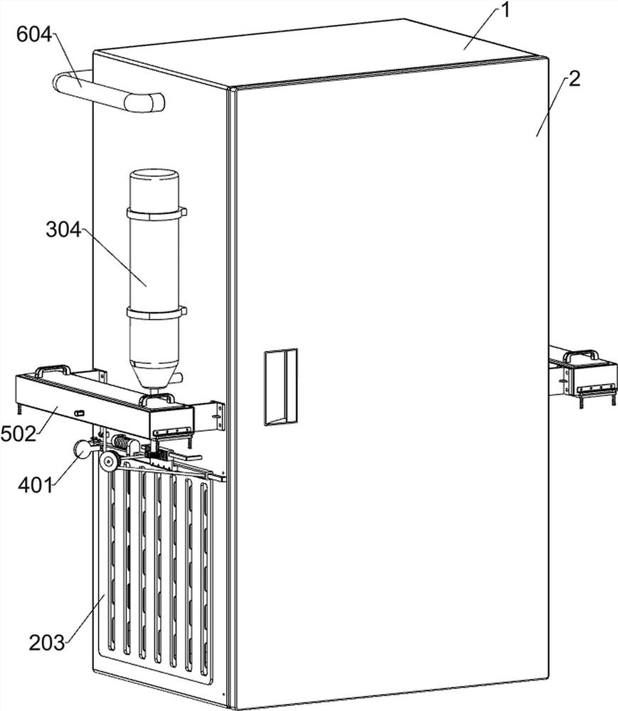
Figure 3
Abstract
Description
technical field
[0001] The invention relates to the field of protection of power cabinets, in particular to an emergency protection device for power cabinets with fire-retardant and flame-retardant functions. Background technique
[0002] In the prior art, when the power cabinet is used in a high-temperature environment, the power module inside the power cabinet will overheat and short-circuit, resulting in spontaneous combustion of the power cabinet. During the use of the power cabinet, the door of the cabinet is closed, ready for fire extinguishing operation. When the fire is damaged, the staff needs to open the box door and then use a fire extinguisher to put out the power module inside. However, the box door of the power cabinet is in a high temperature state during the combustion. Manual direct contact with the box door is prone to burns, and the power module of the power cabinet burns. When the power module is installed, the flame will escape from the heat dissipation ...
Examples
Embodiment 1
[0032] An emergency protection device for power cabinets with fire and flame retardant functions, such as Figure 1-11 As shown, it includes a box body 1, a box door 2, a power module 3, a closing component, an inflatable component, a fixing component and a fire extinguishing component; the box body 1 is installed with a box door 2 on the front side; the rear side of the inner wall of the box body 1 is installed with a power module 3; the lower part of the box body 1 is installed with a closing component; the upper left and right upper parts of the box body 1 are installed with an inflatable component; both the inflatable components are connected with the closing component; the left rear part and the right rear part of the box body 1 A fixed component is installed on each; both fixed components are connected with the closing component; a fire extinguishing component is installed in the left middle part and the right middle part of the box 1; the two fire extinguishing component...
Embodiment 2
[0039] On the basis of Example 1, as Figure 1-3 and Figure 12-13 As shown, it also includes a filter assembly, a filter assembly is installed at the rear of the box 1, and the filter assembly includes a second pipeline 601, a filter 602, a pump body 603, a third pipeline 604, a fourth pipeline 605 and a fifth pipeline 606 The upper part of the right side of the box body 1 is connected with a second pipeline 601; the right part of the rear side of the box body 1 is installed with a filter 602; the filter 602 is communicated with the second pipeline 601; The input end of the pump body 603 is communicated with the second pipeline 601; the output end of the pump body 603 is communicated with a third pipeline 604; A fifth pipe 606 is fixedly connected to the bottom of the inner side of the box body 1; the lower end of the third pipe 604 passes through the box body 1 and communicates with the fifth pipe 606; the fifth pipe 606 is provided with a number of small holes.
[0040] A...