
Adjusting method and adjusting device for transmission shaft intermediate support
A technology of intermediate support and adjustment method, applied in the direction of control device, transportation and packaging, vehicle parts, etc., can solve the problem of poor control accuracy of equivalent angle adjustment, and achieve the effect of improving accuracy
Patent Information
- Authority / Receiving Office
- CN · China
- Current Assignee / Owner
- Publication Date
- 2022-07-22
Smart Images
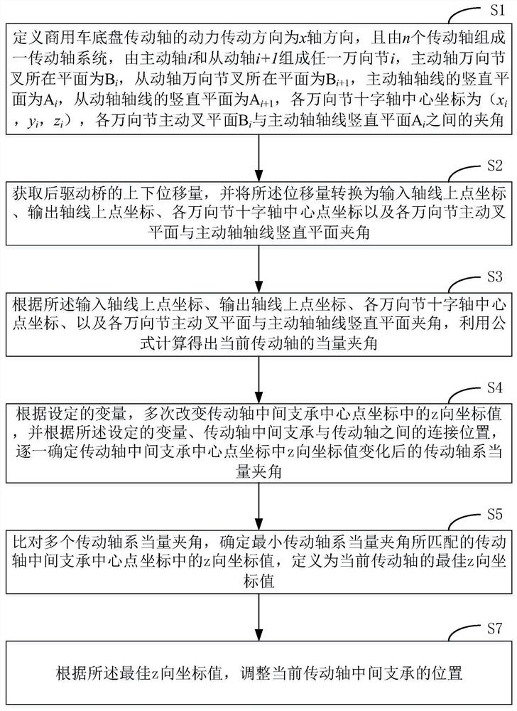
Figure 1 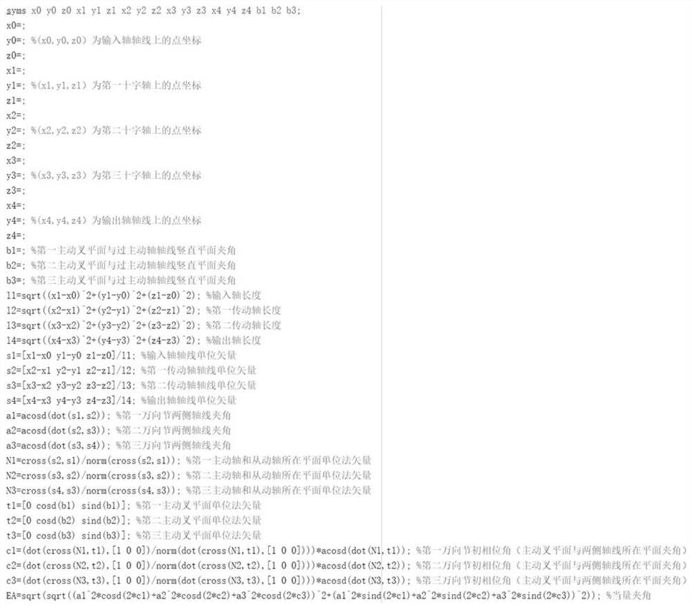
Figure 2 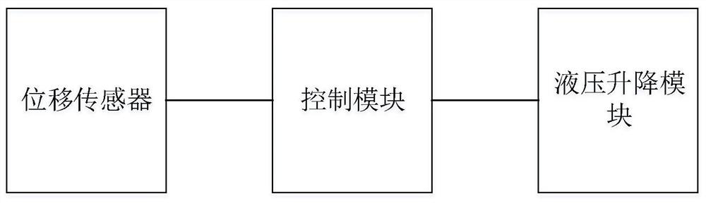
Figure 3
Abstract
Description
technical field
[0001] The present application relates to the technical field of transmission shafts of commercial vehicle chassis, and in particular, to an adjustment method and an adjustment device for the intermediate support of the transmission shaft. Background technique
[0002] In the field of commercial vehicle chassis drive shaft technology, the cross shaft universal joint is widely used because of its high reliability and low cost. In a drive shaft including a universal joint, the parameter for comprehensive evaluation of the drive shaft arrangement is the equivalent angle. When the equivalent angle of universal joint transmission is not zero, the rotational speed of the drive shaft will fluctuate, and at the same time, the bending moment of the fluctuating attachment will be generated on the drive shaft. The fluctuation of rotational speed will cause the gear tooth impact and noise of the transmission system, thus affecting the reliability of the transmission sha...
Examples
Embodiment 1
[0056] see figure 1 , figure 1 This is a schematic flowchart of an adjustment method for an intermediate support of a transmission shaft provided by an embodiment of the present application. Depend on figure 1 It can be seen that the adjustment method for the intermediate support of the transmission shaft in this embodiment mainly includes the following processes:
[0057] S1: Define the power transmission direction of the drive shaft of the commercial vehicle chassis as the x-axis direction, and a drive shaft system is composed of n drive shafts. Any universal joint is formed by the driving shaft and the corresponding driven shaft. The driving shaft is universal The plane where the yoke is located is B i , the plane of the driven shaft universal joint fork is B i+1 , the vertical plane of the drive shaft axis is A i , the vertical plane of the driven shaft axis is A i+1 , the center coordinate of each universal joint cross axis is (x i , y i ,z i ), each universal jo...
Embodiment 2
[0077] exist figure 1 and figure 2 On the basis of the embodiment shown, see image 3 , image 3 This is a schematic structural diagram of an adjusting device for intermediate support of a transmission shaft provided in an embodiment of the present application. Depend on image 3 It can be known that the adjusting device used for the intermediate support of the transmission shaft in this embodiment mainly includes a hydraulic lifting module, a displacement sensor and a control module. The adjusting device in this embodiment is applied to the drive shaft of a commercial vehicle chassis.
[0078] Among them, the displacement sensor is used to measure the up and down displacement of the rear drive axle, and convert the displacement into the coordinates of the points on the input axis, the coordinates of the points on the output axis, the coordinates of the center point of the cross shafts of each universal joint, and the plane of the active fork of each universal joint. The...