
Moving device of yarn pushing mechanism and adjusting method
A motion device and active technology, applied in textiles and papermaking, knitting, warp knitting, etc., can solve problems such as complex structure of plane linkage mechanism, complex structure design, complex motion requirements, etc., and achieve accurate and reliable calculation results and high transmission power Large, wide range of effects
Patent Information
- Authority / Receiving Office
- CN · China
- Patent Type
- Applications(China)
- Current Assignee / Owner
- Publication Date
- 2022-08-05
Smart Images
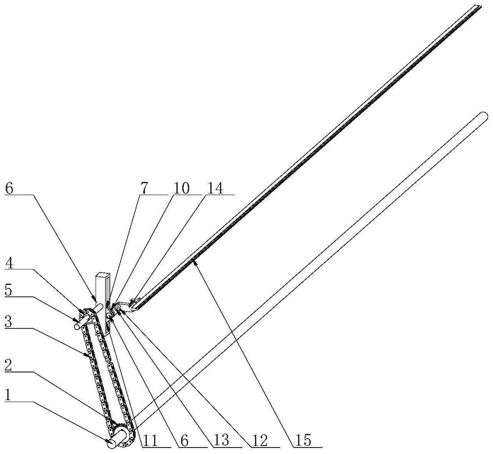
Figure 1 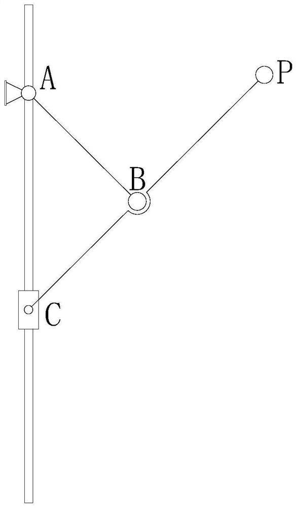
Figure 2 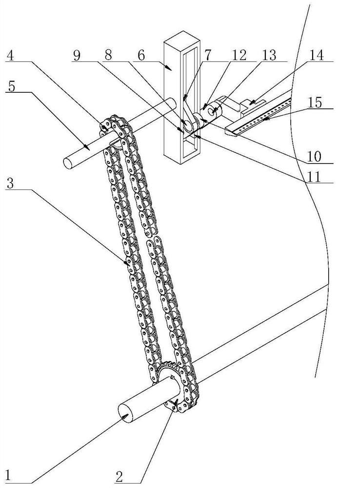
Figure 3
Abstract
Description
technical field
[0001] The invention relates to the field of yarn pushing mechanisms, in particular to a motion device of a yarn pushing mechanism. Background technique
[0002] When using an axial warp knitting machine for production, in order to obtain the target fabric, a fixed positional relationship must be formed between the warp yarns and the axial yarns. To achieve this purpose, the weft-inserted yarns need to be along the axial warp knitting machine. The weft-inserted yarn is pushed to the specified position in the warp direction, so that it is fixed by the braided chain. The mechanical structure for realizing this process is called the yarn-pushing motion device, and in the prior art, most of the mechanical devices for this motion process use One or more sets of plane linkages are realized, and the motion requirements to be realized by the mechanism are complex, and the structure of the plane linkages required is relatively complex, so such a yarn pushing mechanism...
Examples
Embodiment 1
[0015] The existing warp knitting machine has the disadvantages of numerous driving components, complex mechanism composition and large space occupied by the connecting rod box.
[0016] see Figure 1-3 , this embodiment provides a movement device for a yarn pushing mechanism, including an active input shaft 1, the active input shaft 1 is keyed to a drive sprocket 2, and the drive sprocket 2 is connected by a flat key, which can be easily disassembled and assembled. Well, the driving sprocket 2 is meshed with the driven sprocket 4 through the chain 3, the driven sprocket 4 is keyed to the driven input shaft 5, the driven input shaft 5 is provided with a guide rail frame 6, and the guide rail frame 6 is fixed on the operating table. On one side, the guide rail frame 6 is provided with three grooves, which can provide a limiting effect on the driven input shaft 5 and the first yarn pushing rod 10 respectively. The driven input shaft 5 is rotatably connected with the drive shaft ...