
Electric vehicle structure
A technology of electric vehicles and electric drive wheels, which is applied in the field of electric vehicles, can solve the problems of a wide range of enthusiasts, and achieve the effect of stable operation
Patent Information
- Authority / Receiving Office
- CN · China
- Patent Type
- Applications(China)
- Current Assignee / Owner
- Publication Date
- 2003-09-10
- Estimated Expiration
- Not applicable · inactive patent
Smart Images
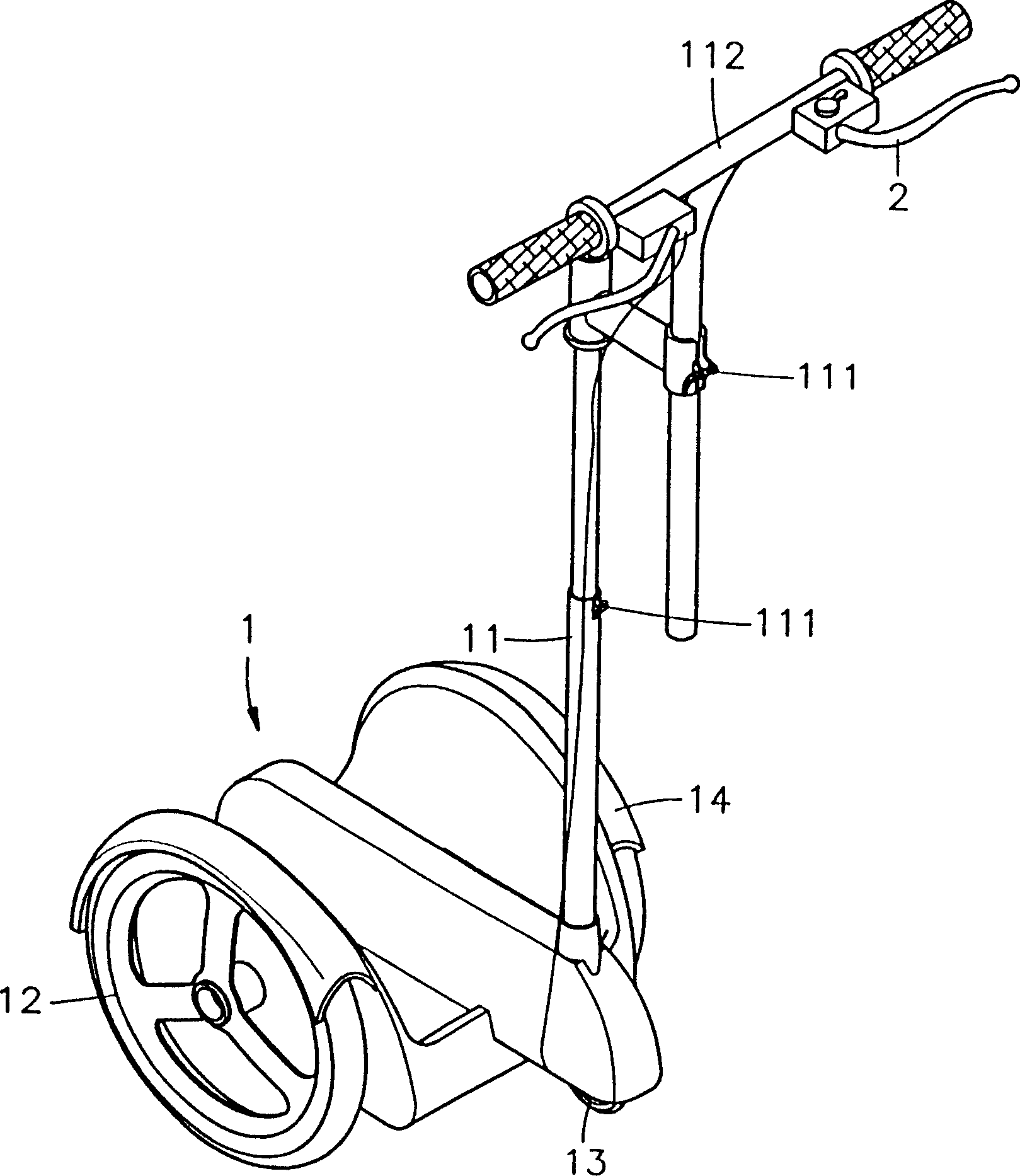
Figure 1 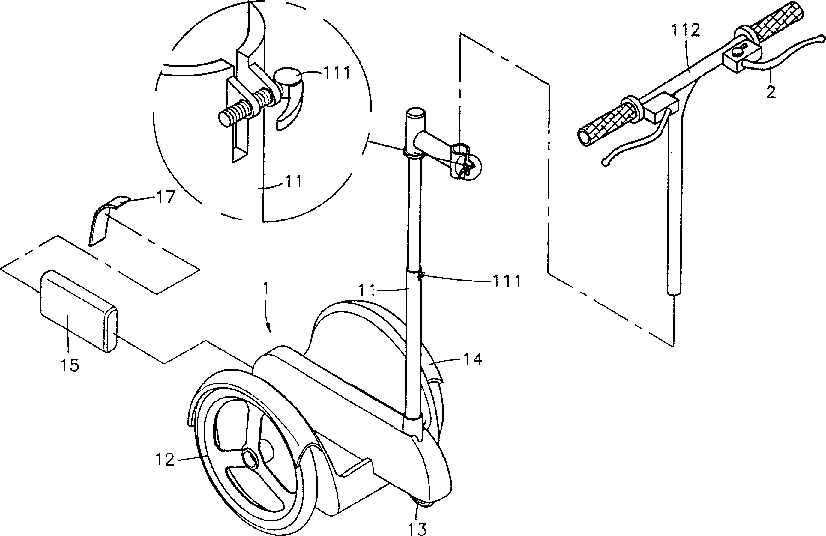
Figure 2 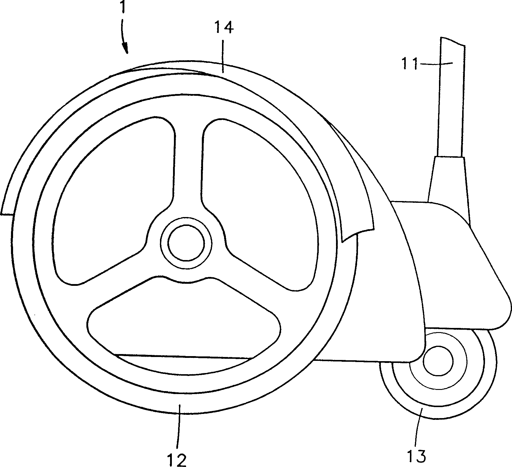
Figure 3
Abstract
Description
Technical field
[0001] The invention relates to an electric vehicle structure, in particular to an electric vehicle with a power assist device. Background technique
[0002] Nowadays, the society vigorously advocates environmental protection and air purification, and vehicles are moving towards electric startup as the main research direction. However, the continuous research, improvement and innovation of related industries have prompted the emergence of various functions and types of electric vehicle products. So that consumers have a more diversified choice, currently used scooters, such as Figure 5 Shown is a three-dimensional appearance view of a conventional embodiment. The figure reveals that the structure of this scooter is composed of a seat body A and a connecting rod A1 pivotally connected to the seat body A. The seat body A has two front and rear sides. An auxiliary wheel A2 is pivoted on each side, and the auxiliary wheel A2 pivoted on the front side is connected wit...
Examples
Embodiment Construction
[0017] In order to achieve the above-mentioned purpose and structure, the technical means adopted by the present invention and its effects, the steps and functions of the preferred embodiments of the present invention are described in detail as follows to facilitate a complete understanding.
[0018] Such as Figure 1~3 Shown are the three-dimensional appearance view, the three-dimensional exploded view and the side view of the present invention. It can be seen from the figures that the present invention is composed of a base 1 and a control link 11 pivotally connected to the base 1, wherein:
[0019] An auxiliary wheel 12 is set on both sides of the seat body 1, and an electric drive wheel 13 with a smaller outer diameter is arranged in front of the center of the two auxiliary wheels 12, and is connected with the bottom end of the control link 11, and the control link The rod 11 is a multi-piece movable telescopic tube design, and is connected by a quick release fastener 111, and ...