
Welding mask
A welding mask and face protection technology, applied in welding accessories, eye masks, eye surgery, etc., can solve problems such as trouble, and achieve high operability and work efficiency, high efficiency, and easy operation.
Patent Information
- Authority / Receiving Office
- CN · China
- Current Assignee / Owner
- Publication Date
- 2005-05-04
- Estimated Expiration
- Not applicable · inactive patent
Smart Images
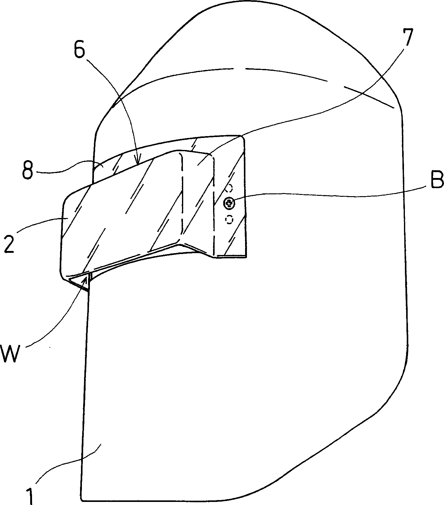
Figure 1 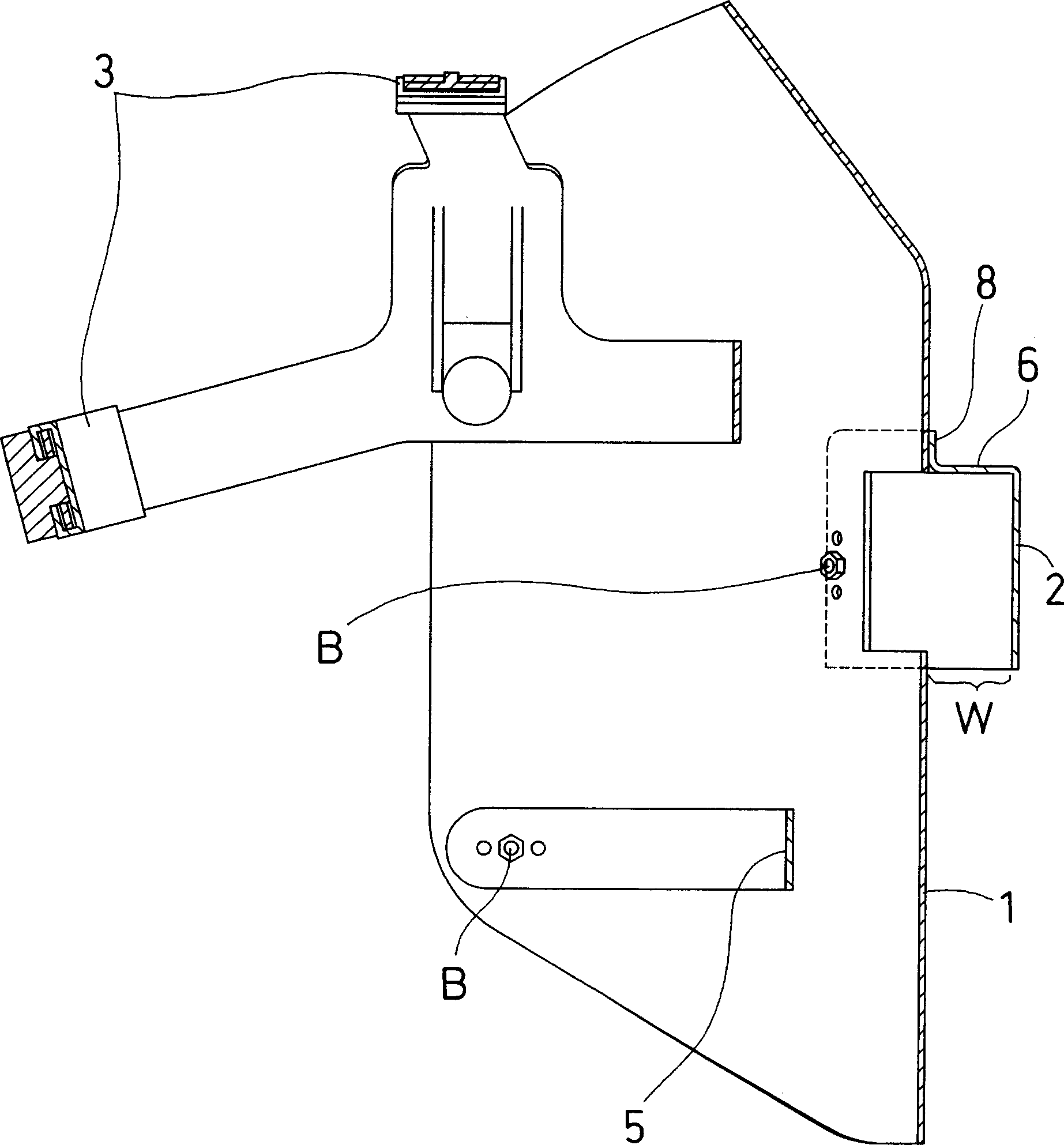
Figure 2 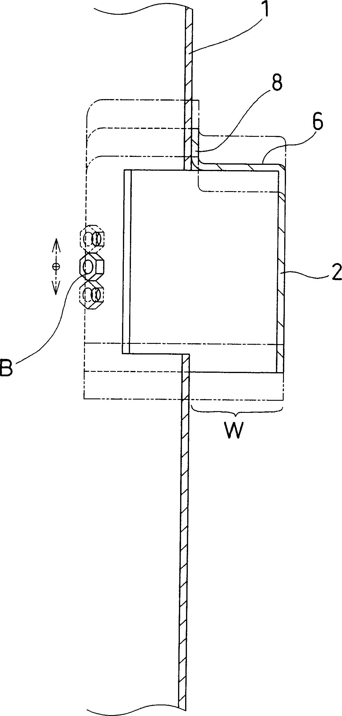
Figure 3
Abstract
Description
technical field
[0001] The present invention relates to a welding mask for use in welding operations. Background technique
[0002] Currently, welding masks are used to protect the eyes and the skin of the face during welding operations. (For example, as shown in Non-Patent Document 1).
[0003] Such as Figure 21 and Figure 22 As shown, the current welding mask also has a head-mounted form. The front of the main body part 21 is fixed with a transparent protective lens 22, and a light-shielding goggle lens 24 is designed on its outside, which can be freely opened on the aforementioned protective lens 22 by a spring 23. combine.
[0004] In the welding operation, it is necessary to adjust the correct positional relationship of the welding object, and the welding operation can only be performed after the positional relationship is correct. Here, if Figure 21 As shown, when adjusting the positional relationship of the object, the shading goggle lens 24 that is dark and ha...
Examples
Embodiment 1
[0059] Such as Figure 1 to Figure 5 As shown, in the welding mask of this embodiment, the light-shielding goggle lens 2 protruding from the surface of the face protection part 1 worn on the head is formed to block welding flash, and it is made of light-shielding synthetic resin. The aforementioned face protector 1 is made of high-temperature-resistant paper material, worn on the head through a fitting part 3 , and adjusted by a knob 4 . The face protection part 1 is fixed with the jaw support part 5 (such as figure 2 shown).
[0060] The observation part W protruding below the above-mentioned protruding light-shielding goggle lens 2 is a part without light-shielding properties, such as Figure 4 As shown, the welding object can be observed and its position can be adjusted through the light-transmitting part.
[0061] That is, in order to remove the light-shielding property of the observation portion W protruding below the protruding light-shielding goggle lens 2 , the pro...
Embodiment 2
[0068] The difference between the welding mask of the present embodiment and the foregoing embodiment 1 is that the aforementioned face protection part 1 is provided with a concave shape along the shape of the face on a certain area below the protruding light-shielding goggle lens 2 .
[0069] Such as Figure 6 to Figure 11 As shown, in the welding mask of this embodiment, the light-shielding goggle lens 2 protruding from the surface of the face protection part 1 worn on the head blocks welding flashes and is made of a synthetic resin with light-shielding properties. The aforementioned face protection part 1 is made of high temperature resistant paper material, is worn on the head through the wearing part 3, and is adjusted by the knob 4. The face protection part 1 is fixed with the jaw support part 5 (such as Figure 7 , Figure 8 shown).
[0070] The observation part W protruding below the above-mentioned protruding light-shielding goggle lens 2 is a part without light-sh...
Embodiment 3
[0081] The welding mask of this embodiment differs from the foregoing in that it has an extension 10 protruding obliquely forward from the lower end edge of the light-shielding goggle lens 2 .
[0082] Such as Figure 12 to Figure 18 Shown, the welding mask of the present embodiment, the light-shielding goggle lens 2 of the light-shielding property synthetic resin system that its face protector 1 surface blocks welding flash is installed on the window H that fixed mount 11 offers (as Figure 15 shown). Here, the shading goggle lens 2, such as Figure 17 , 18 As shown, a pair of L-shaped metal parts 13 with springs on the left and right can realize free assembly and disassembly. The aforementioned L-shaped metal part 13 with a spring is an L-shaped hinge structure formed by connecting two pieces of metal through a spring S, one of which is installed on the fixed frame 11 with a screw B, and the other can be bounced under the action of a spring. back. Therefore, the shading...