
Electric power source system
a power source and electric power technology, applied in secondary cell servicing/maintenance, safety/protection circuits, batteries, etc., can solve the problems of increasing the electric power consumption of the electrical load, affecting the operation of the vehicle, so as to reduce the deterioration of drivability and the effect of rapid change of regenerative electric power
Patent Information
- Authority / Receiving Office
- US · United States
- Patent Type
- Patents(United States)
- Current Assignee / Owner
- Publication Date
- 2020-04-07
Smart Images
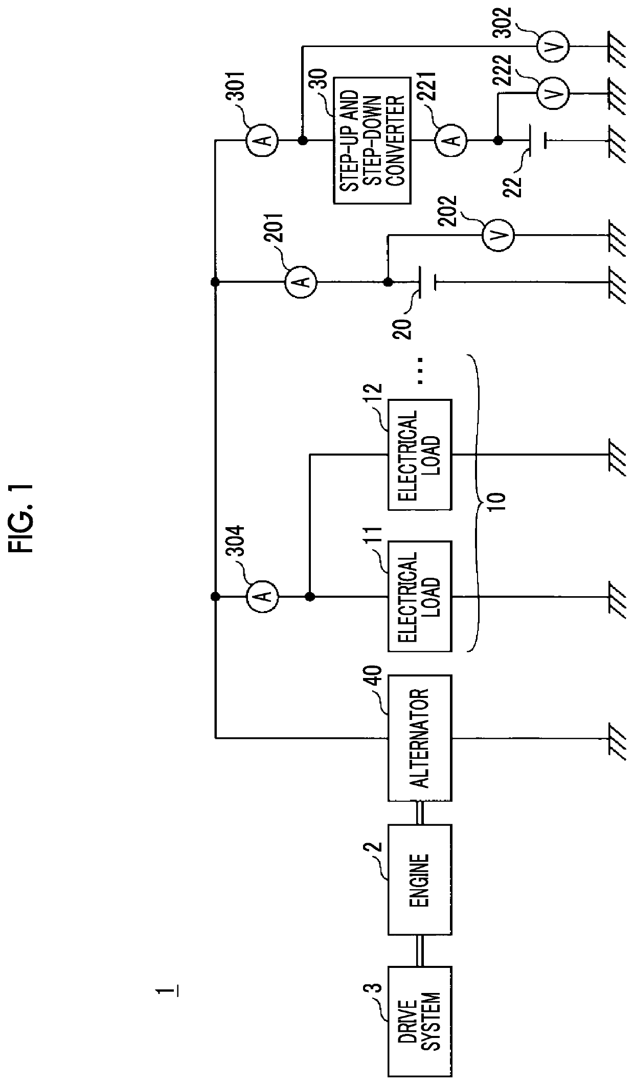
Figure 1 
Figure 2 
Figure 3
Abstract
Description
INCORPORATION BY REFERENCE
[0001] The disclosure of Japanese Patent Application No. 2017-015673 filed on Jan. 31, 2017 including the specification, drawings and abstract is incorporated herein by reference in its entirety.BACKGROUND1. Technical Field
[0002] The present disclosure relates to an electric power source system.2. Description of Related Art
[0003] In a known technology (refer to, for example, Japanese Unexamined Patent Application Publication No. 2013-162645 (JP 2013-162645 A)), the electric power of an auxiliary device that is consumed as electric power regenerable by an electric motor is restricted with a predetermined upper limit value of the electric power of the auxiliary device determined in accordance with a vehicle speed, when a traveling condition that the deceleration of a vehicle is changed due to a decrease in the electric power consumption of the auxiliary device is established during execution of cooperative regenerative brake control.SUMMARY
[0004] In a regenerativ...
Examples
Embodiment Construction
[0029]Hereinafter, an embodiment will be described in detail with reference to the appended drawings.
[0030]FIG. 1 is a diagram illustrating a schematic electric circuit configuration of an electric power source system 1. The electric power source system 1 is mounted in a vehicle that includes an engine 2 as a drive source. A drive system 3 such as a transmission is mechanically connected to the engine 2.
[0031]The electric power source system 1 includes an electrical load group 10, a lead battery 20, a lithium ion battery 22, a DC-DC converter 30 (hereinafter, referred to as a “step-up and step-down converter 30”), and an alternator 40. The step-up and step-down converter 30 is a voltage conversion device that converts the voltage of a direct current.
[0032]The electrical load group 10 includes a plurality of electrical loads 11, 12 of a low voltage system that is supplied with electric power from the lead battery 20. While the electrical load group 10 includes two electrical loads 11...