
Propeller shaft
a technology for propeller shafts and shaft assemblies, which is applied in the direction of shafts, rotating vibration suppression, shafts and bearings, etc., can solve the problems of relatively high rotational speed of propeller shafts, and achieve the effects of improving structural rigidity, increasing the bending frequency of propeller shaft assemblies, and reducing the weight of supporting members
Patent Information
- Authority / Receiving Office
- US · United States
- Current Assignee / Owner
- Publication Date
- 2005-02-24
- Estimated Expiration
- Not applicable · inactive patent
Smart Images
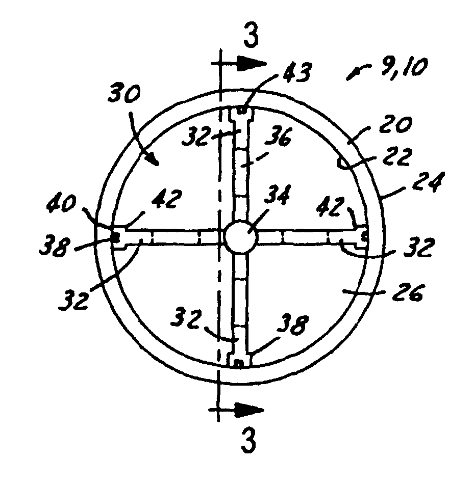
Figure 1 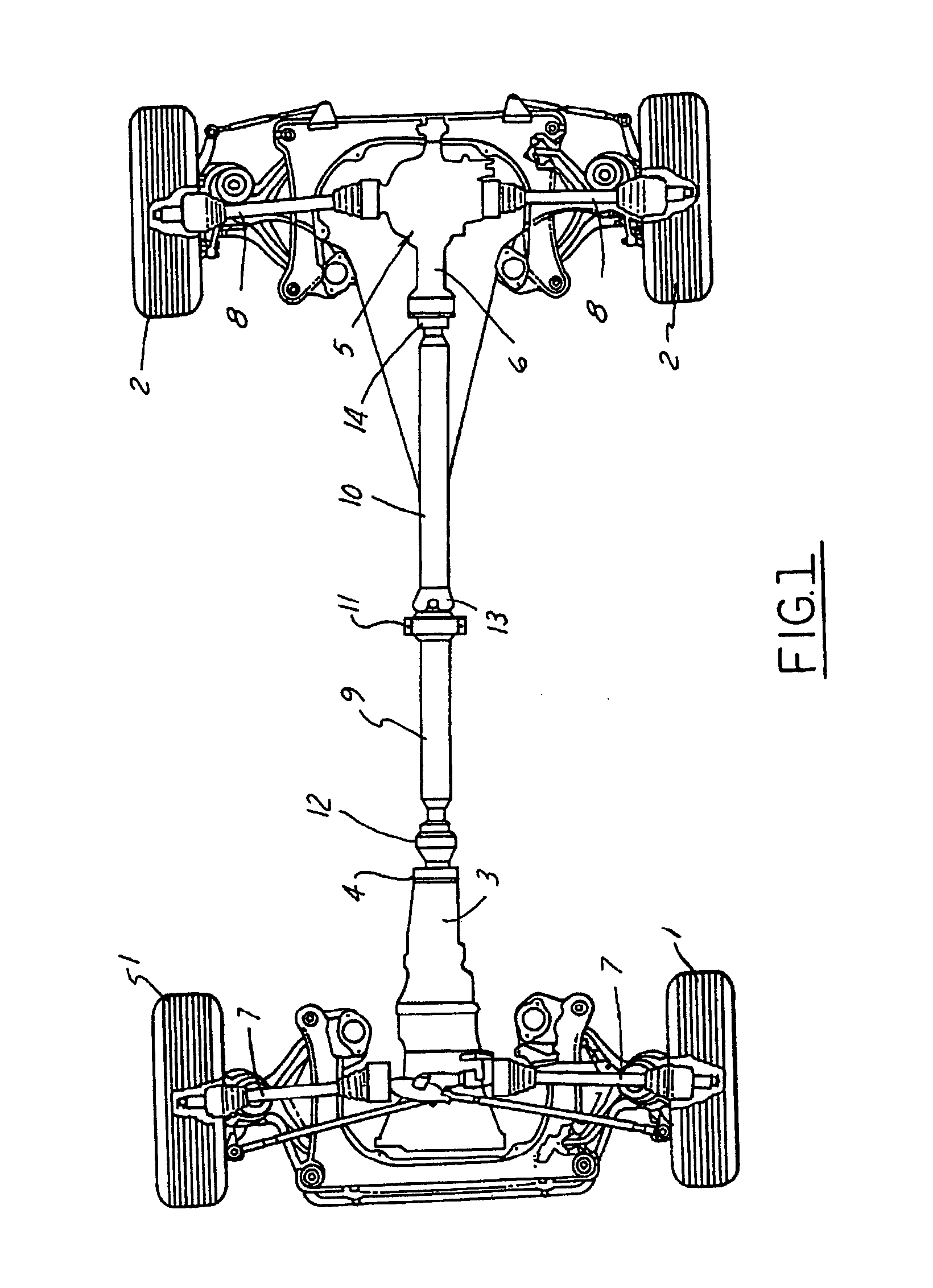
Figure 2 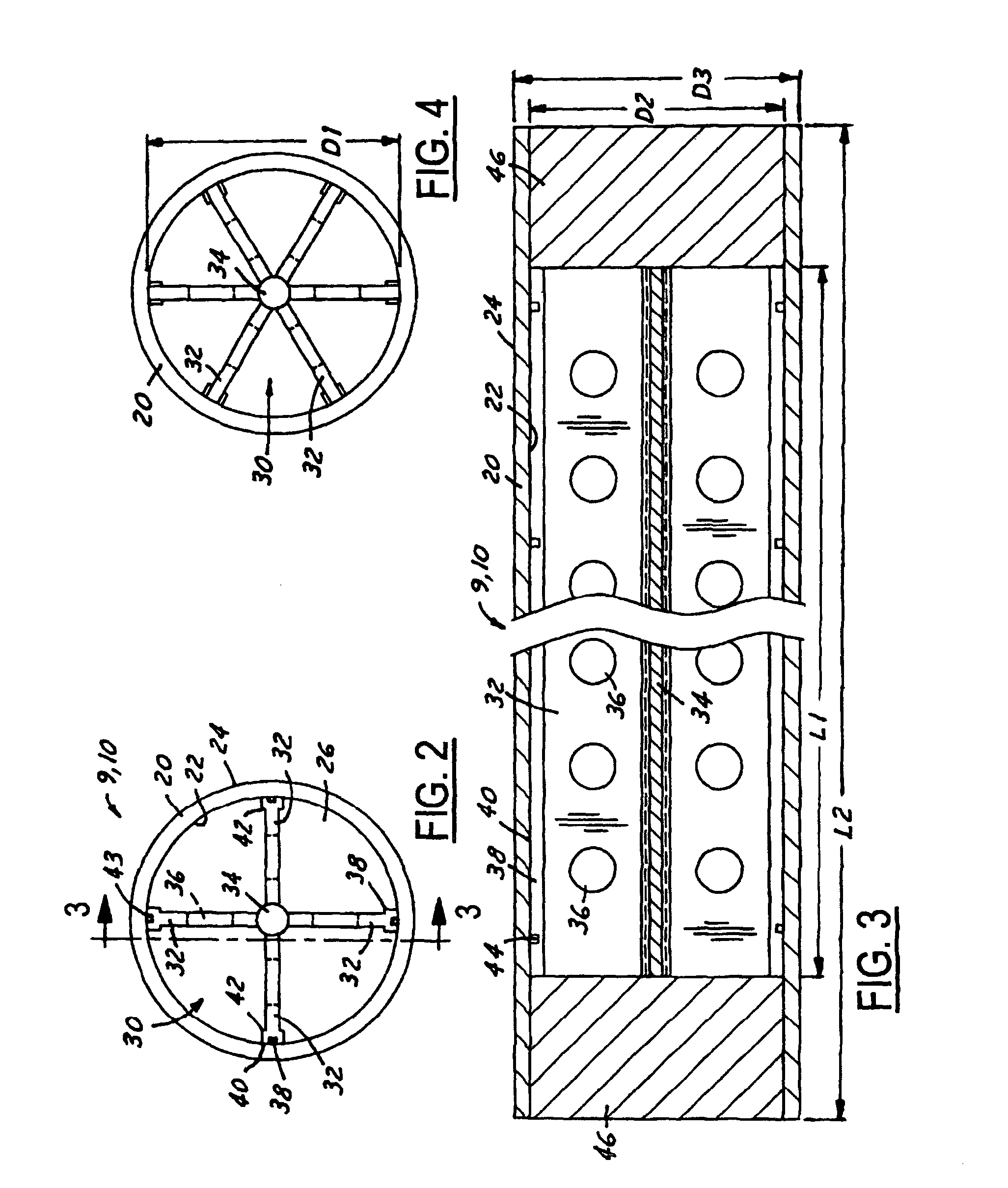
Figure 3
Abstract
Description
TECHNICAL FIELD
[0001] The present invention relates to propeller shaft assemblies for motor vehicles. In particular, the invention concerns a driveline propeller shaft assembly with a stiffening feature. BACKGROUND OF THE INVENTION
[0002] Vehicle drivelines typically include constant velocity joints, cardan joints, side shafts and propeller shafts in various configurations to provide motive power for the vehicle. Constant velocity fixed joints are known in various designs. Such joints are used primarily in the driveline of a motor vehicle for driving the wheels of a motor vehicle. They can be used in either propeller shafts or in side shafts. Side shafts extend from the axle drive to the driven wheels; for example, they connect the output ends of the rear axle differential with the driven wheel hubs of the wheels. Propeller shafts serve to transmit the drive from the gearbox output of the front wheel drive unit to the rear axle differential associated with the rear axle.
[0003] As ...
Examples
Embodiment Construction
[0017] In the following description, various operating parameters and components are described for one constructed embodiment. These specific parameters and components are included as examples and are not meant to be limiting.
[0018] While the invention is described with respect to a propeller shaft having improved rigidity within the driveline of a vehicle, the following apparatus is capable of being adapted to various purposes including automotive vehicles, motor systems that use a propeller shaft, or other vehicle and non-vehicle applications which require a rigid torque-transmitting shaft. Referring now to the drawings wherein like reference numerals are used to identify identical components of the various views, FIG. 1 illustrates a diagrammatic view of an exemplary driveline of a motor vehicle having a propeller shaft assembly in which the present invention may be used to advantage. The driveline assembly of FIG. 1 is illustrative of the environment in which a propeller shaft ...