
Optical devices particularly for remote viewing applications
a technology for remote viewing and optical devices, applied in the field of optical devices, can solve the problems of limited performance, heavy hud systems, and many significant drawbacks of the current hud system, and achieve the effects of convenient structure and fabrication, compact and simple modules, and high fov
Patent Information
- Authority / Receiving Office
- US · United States
- Current Assignee / Owner
- Publication Date
- 2005-04-14
Smart Images
Figure 1 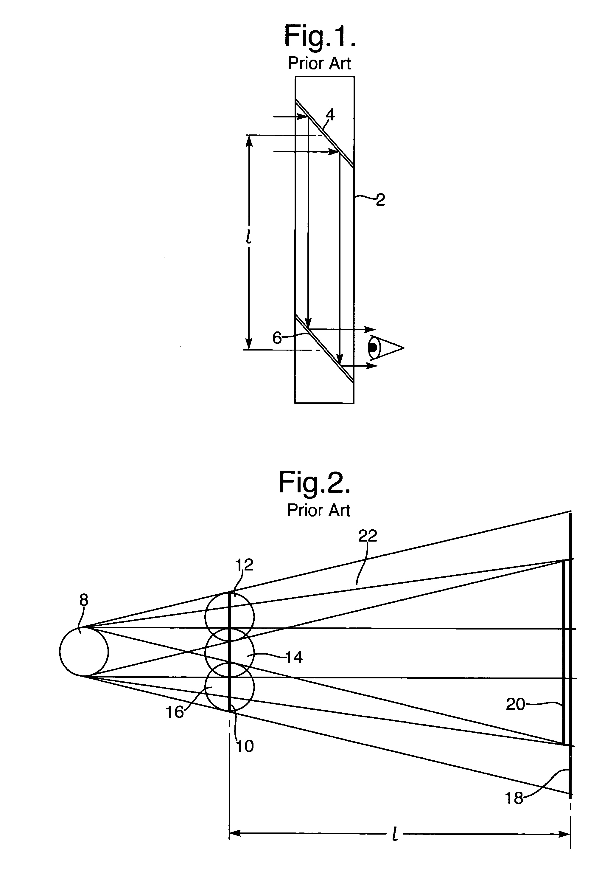
Figure 2 
Figure 3
Abstract
Description
FIELD OF THE INVENTION The present invention relates to optical devices, and in particular to devices whereby an object is viewed remotely, with a large field-of-view (FOV) and in which the system aperture is limited by various constrains. The invention can advantageously be implemented in a large number of imaging applications, such as periscopes, as well as head-mounted and head-up displays. BACKGROUND OF THE INVENTION There are many applications in which remote viewing is necessary, as the object to be viewed is located in an environment hostile to the viewer, or it is inaccessible to the viewer without causing unacceptable damage to its environment. Periscopes for military applications fall into the former category, while endoscopes, colonoscopes, laryngoscopes and otoscopes, for medical applications, fall into the latter. An additional category is that of see-through imaging systems, such us head-mounted displays (HMDs) and head-up displays (HUDs), wherein the optical combin...
Examples
Embodiment Construction
Remote viewing optical systems, and periscopes in particular, are optical systems designed to displace the object space reference point away from the eye space reference point. This allows the observer to look over or around an intervening obstacle, or to view objects in a dangerous location or environment while the observer is in a safer location or environment. A submarine periscope is the typical example, but many other applications, both military and non-military, are envisioned.
FIG. 1 illustrates the simplest form of a prior art periscope 2, having a pair of optical elements 4 and 6, e.g., a pair of folding mirrors, which are used to allow a viewer to see over a nearby obstacle. The basic geometry of this embodiment imposes limitations on the performance of the system. This is especially true for systems with a very wide FOV and a constraint on the distance, l, between the folding-in optical element 4 and the folding-out element 6.
FIG. 2 illustrates an unfolded optical syste...