
Communication terminal
Patent Information
- Authority / Receiving Office
- US · United States
- Current Assignee / Owner
- Publication Date
- 2006-01-26
- Estimated Expiration
- Not applicable · inactive patent
Smart Images
Figure 1 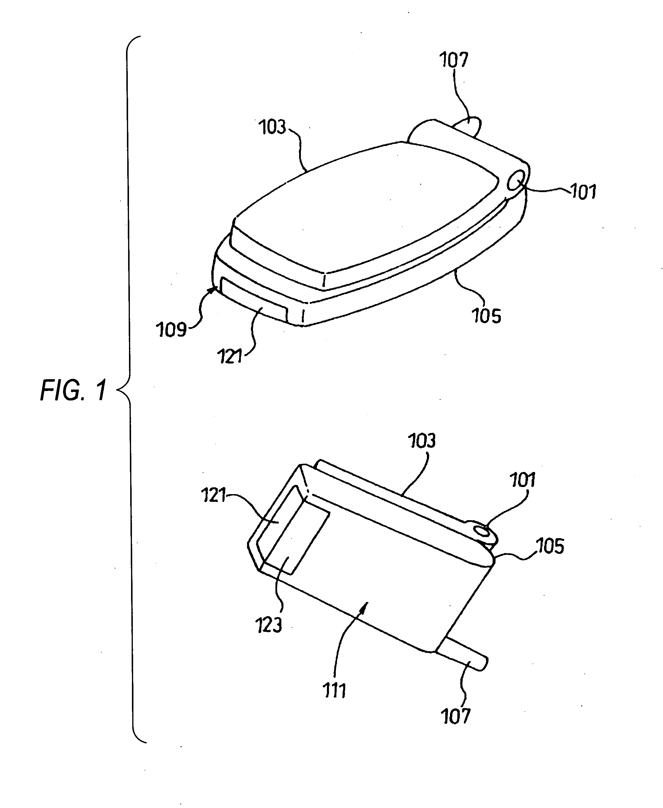
Figure 2 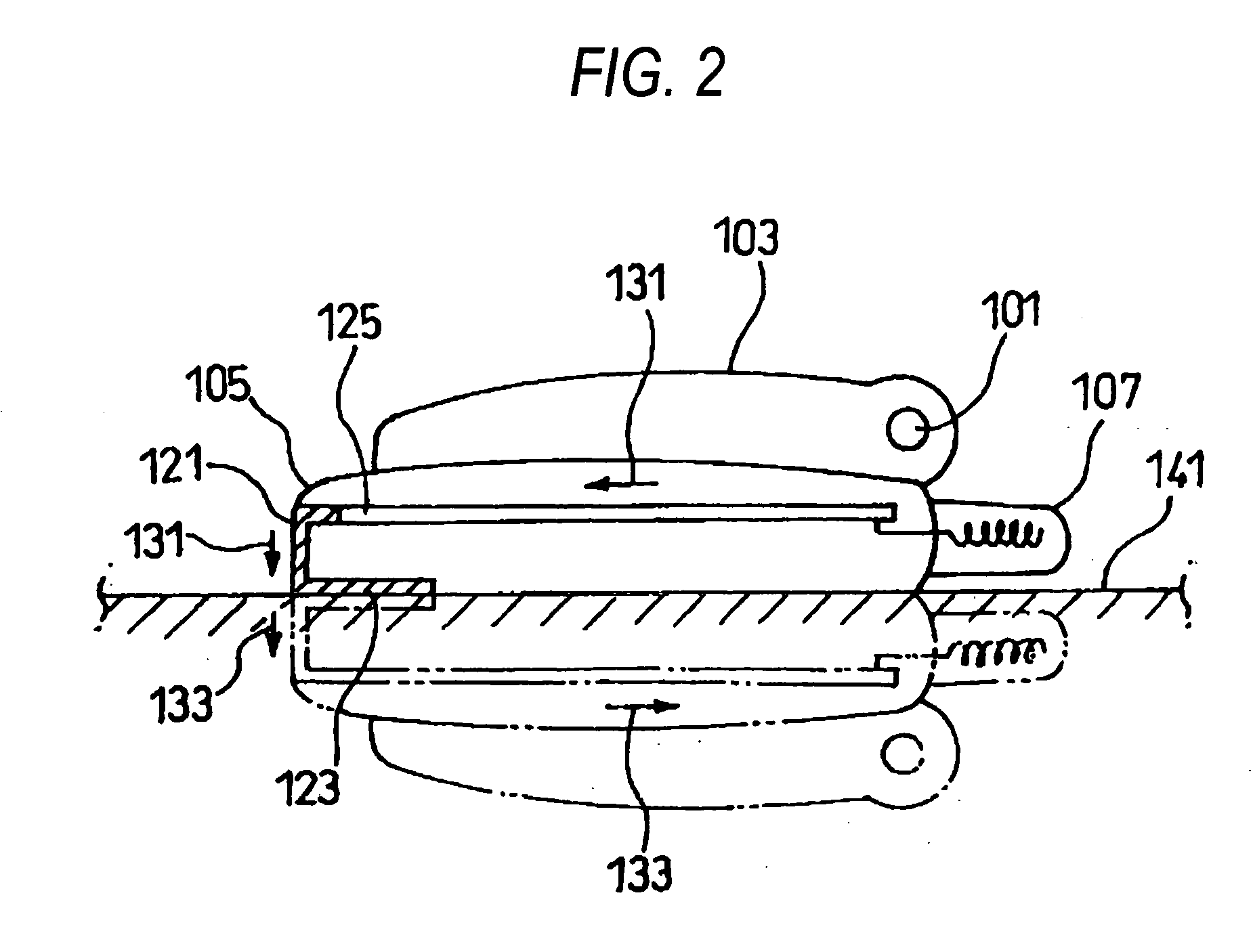
Figure 3
Abstract
Description
Technical Field
[0001] This invention relates to a communication terminal and in particular to a communication terminal capable of keeping the reception sensitivity good if the communication terminal is placed on a metal plate of a steel desk, etc., in a state in which the communication terminal is laid on its side. BACKGROUND ART
[0002] Usually, a communication terminal such as a mobile telephone or a PHS is provided with an antenna. If the communication terminal is placed on a metal plate of a steel desk, etc., with the communication terminal laid on its side, the antenna is brought close to the metal plate and thus interconnection occurs and a current of an opposite phase to the current flowing through the antenna flows into the metal face, changing the radiation directivity of the antenna and largely changing the impedance characteristic. Thus, the matching state comes undone and the antenna gain is degraded; this is a problem.
[0003] To solve this problem, a small radio describ...
Examples
first embodiment
[0027]FIG. 1 is an external view to show a communication terminal of a first embodiment. As shown in the figure, the communication terminal of the embodiment has two foldable casings (upper casing 103 and lower casing 105) joined by a hinge 101 and an antenna 107 installed on the lower casing 105. A bottom surface of the lower casing 105 denoted by numeral 109 in FIG. 1 and a rear denoted by numeral 111 are formed roughly at the right angle. A radiating element 121 corresponding to a second conductor part in claims is provided so that it is exposed flush with the bottom surface 109 of the lower casing 105, and an auxiliary bottom board 123 corresponding to a first conductor part is provided so that it is exposed flush with the rear 111 of the lower casing 105; the radiating element and the auxiliary bottom board are joined roughly at the right angle. The radiating element 121 and the auxiliary bottom board 123 are conductors.
[0028] The main part of the communication terminal of the...
second embodiment
[0036]FIG. 5 is a schematic representation to schematically show the main part of a communication terminal of a second embodiment from a bottom face. FIG. 6 is a schematic representation to schematically show the communication terminal of the second embodiment from a side (a) and from a rear (b). Parts identical with those in FIGS. 1 and 2 (first embodiment) are denoted by the same reference numerals in FIGS. 5 and 6.
[0037] The communication terminal of the second embodiment is provided with a board 125, metal fittings 201, a radiating element 203, and an auxiliary bottom board 205 inside a lower casing 105, as shown in FIGS. 5 and 6. The radiating element 203 and the auxiliary bottom board 205 are formed in one piece. The metal fittings 201 are fittings for fixing parts 207 of a connector, a jack, etc., to the board 125 and are electrically connected to GND of the board 125. Further, the radiating element 203 is provided with roof-type spring parts 209 to come in contact with the ...
third embodiment
[0041]FIG. 7 is an external view to show a state in which a rear cover of a lower casing of a communication terminal of a third embodiment is removed from the rear. FIG. 8 is a schematic representation to schematically show the main part of the communication terminal of the third embodiment from a side. Parts identical with those in FIGS. 1 and 2 (first embodiment) are denoted by the same reference numerals in FIGS. 7 and 8.
[0042] The communication terminal of the third embodiment is provided with a board 301, a shield case 303 attached to the rear of the board 301, a radiating element 305, and an auxiliary bottom board 307 inside a lower casing 105, as shown in FIGS. 7 and 8. The radiating element 305 and the auxiliary bottom board 307 are formed in one piece on the rear of the lower casing 105 of the board 301. The radiating element 305 is formed in such a manner that a part of the auxiliary bottom board 307 is lifted up from the rear and is pressed against the shield case 303. T...