
LED driving apparatus and method of controlling luminous power
a technology of led driving and luminous power, which is applied in the direction of instruments, static indicating devices, optics, etc., can solve the problems of increased power consumption, low luminous efficiency of led driving, and low luminous efficiency, so as to minimize power consumption, the effect of luminous efficiency and highest luminous efficiency
Patent Information
- Authority / Receiving Office
- US · United States
- Patent Type
- Applications(United States)
- Current Assignee / Owner
- Publication Date
- 2006-04-20
Smart Images
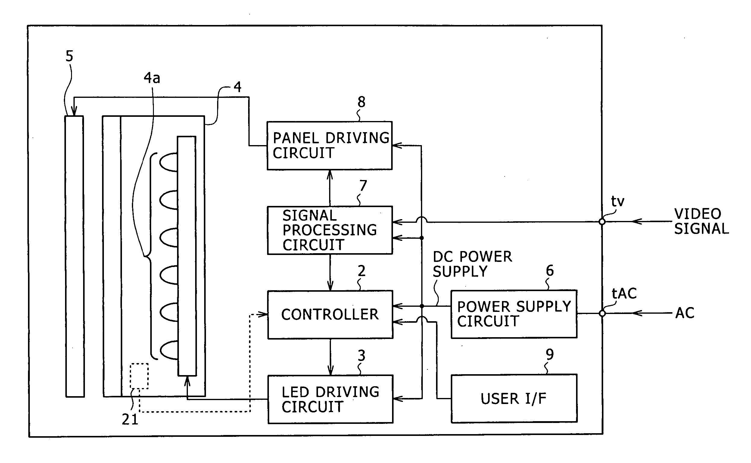
Figure 1 
Figure 2 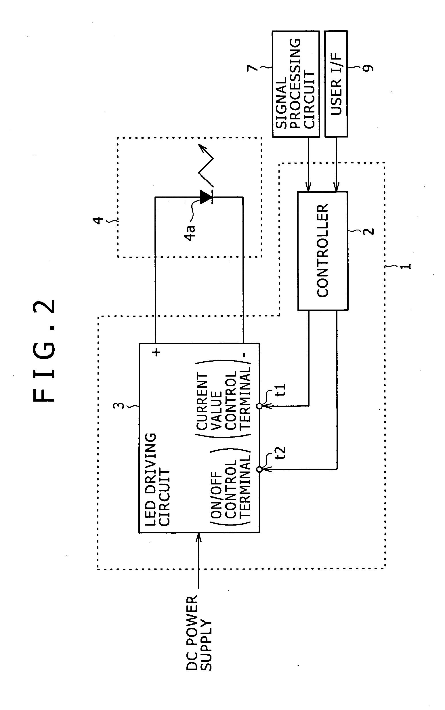
Figure 3
Abstract
Description
CROSS-REFERENCE TO RELATED APPLICATIONS
[0001] The present application claims priority from Japanese Patent Application Nos. JP 2004-296148 filed on Oct. 8, 2004 and JP 2005-227965 filed on Aug. 5, 2005, the disclosures of which are hereby incorporated by reference herein. BACKGROUND OF THE INVENTION
[0002] The present invention relates to an LED driving apparatus and a method of controlling luminous power.
[0003] A display, such as a liquid crystal display, that is not a self-emitting display is provided with a backlight. As such a backlight, one employing cold-cathode tubes as its light source has been known for example. In addition, in recent years, backlights employing light emitting diodes (LEDs), which consume less power, have also been known.
[0004] As a method of controlling the luminous power of such a backlight including LEDs, two kinds of methods have been known. One is a current value control method for controlling the level of a driving current supplied to the LEDs. Ano...
Examples
first embodiment
[0056] Note that the controller 2 and the LED driving circuit 3 constitute the LED driving apparatus 1 as the first embodiment as shown also in FIG. 2.
[0057] The controller 2 sets the target value of the luminous power of the LED 4a according to APL information calculated based on a luminance signal from the signal processing circuit 7 shown also in FIG. 1, and according to an instruction input value if an instruction as to the brightness adjustment is input from the user I / F 9. The controller 2 then supplies a control signal to the current value control terminal t1 or the ON / OFF control terminal t2 of the LED driving circuit 3 so that the luminous power of the target value is obtained.
[0058] The controller 2 of the embodiment stores in advance information of the forward current value (driving current level) providing the highest luminous efficiency and the luminous power value (predetermined value) obtained from the forward current value as to the LED 4a.
[0059] The controller 2 s...
second embodiment
[0087]FIG. 5 illustrates the configuration of an LED driving apparatus 20 as the invention.
[0088] The LED driving apparatus 20 of the second embodiment also implements switching of the luminous power control methods, implemented in the first embodiment. Furthermore, the LED driving apparatus 20 includes a luminous power sensor 21 in addition to the configuration of the LED driving apparatus 1 shown in FIG. 2. The luminous power sensor 21 is provided at a certain place in the backlight 4 so as to detect the luminous power of the LED 4a (the luminous power sensor 21 is represented with a dashed line in FIG. 1).
[0089] Information of the luminous power detected by the luminous power sensor 21 is input to the controller 2.
[0090] The controller 2 controls the luminous power of the LED 4a based on the luminous power value detected and input by the luminous power sensor 21 as well as based on the target value of luminous power set according to a brightness signal from the signal processin...