
Position detection device
Patent Information
- Authority / Receiving Office
- US · United States
- Current Assignee / Owner
- Publication Date
- 2006-09-21
Smart Images
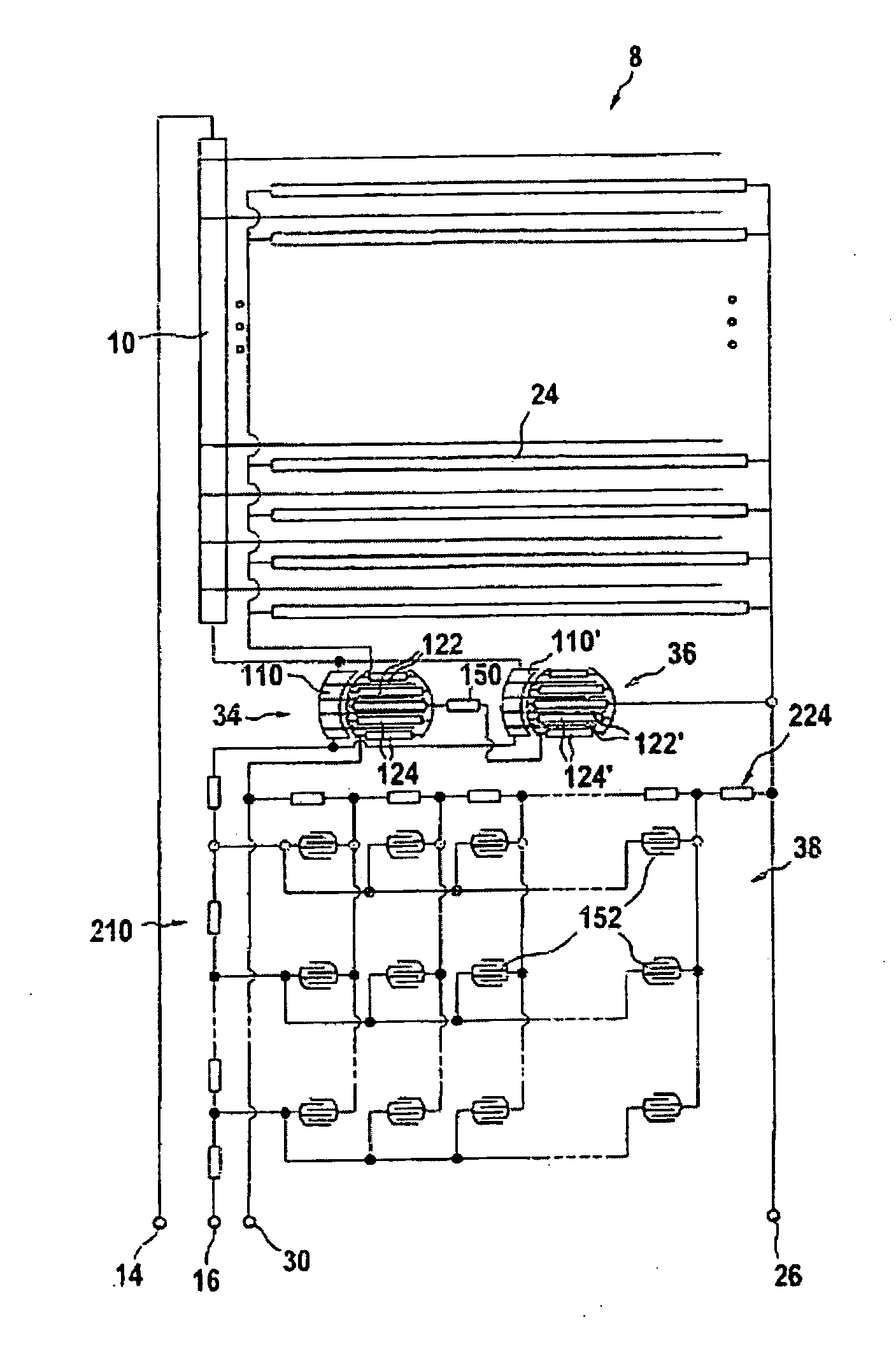
Figure 1 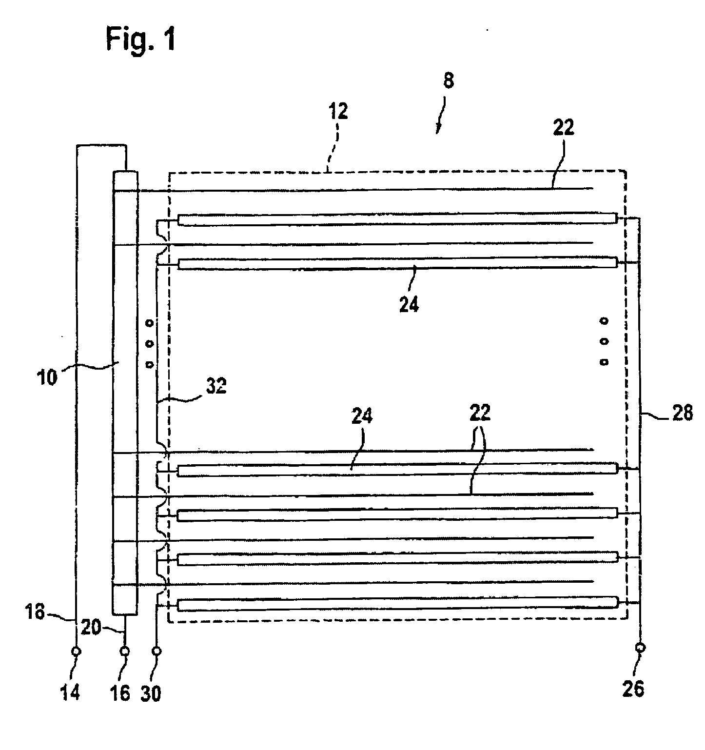
Figure 2 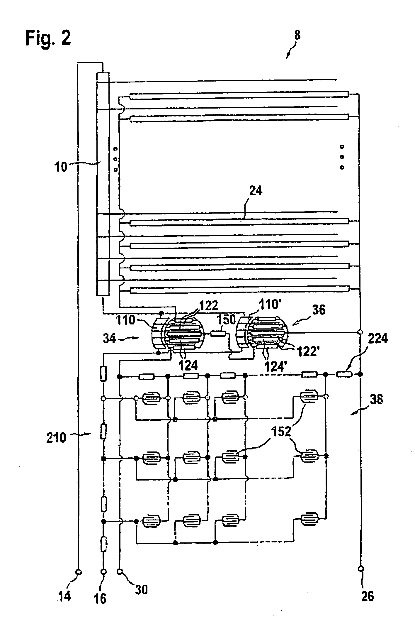
Figure 3
Abstract
Description
INTRODUCTION
[0001] The present invention relates in general to a device for detecting a position where a force acts and, where appropriate, the intensity of this force.
[0002] It is known to construct devices for detecting a position where a force acts on the basis of sheet switches. A sheet switch comprises two support sheets, which are held a certain distance apart using a spacer. The spacer includes at least one recess that defines an active region of the switch, in which the two support sheets face each other. Inside this active region, at least two electrodes are arranged on the support sheets in such a way that an electrical contact is established between the electrodes when the two support sheets are pressed together through the effect of a force acting on the switch.
[0003] Depending on the application, a layer of semiconductor material may be placed between the electrodes, in such a way that the switch exhibits pressure-sensitive behavior, that is to say its resistance var...
Examples
Example
[0031]FIG. 1 shows a view of the arrangement of the conductors on the first substrate of a position detector 8. A linear ohmic resistor 10, which extends along an active surface 12 of the position detector, is placed on a substrate. In the embodiment shown, the active surface has a generally square shape. However, it should be noted that other shapes are possible, for example oval, circular, rectangular, etc.
[0032] The ohmic resistor 10 is connected between a first terminal 14 and a second terminal 16 of said position detection device via conducting lines 18, 20.
[0033] A plurality of electrical conductors 22 are connected to the first ohmic resistor 10 at discrete points thereon, the electrical conductors 22 extending from the first ohmic resistor toward the interior of the active surface 12. In the embodiment shown, the conductors 22 are distributed equidistantly and extend parallel to one another. It goes without saying that a different arrangement of conductors is possible.
[00...