
Electric signal splitters
a technology of electric signals and splitters, applied in the direction of waveguides, waveguide type devices, coupling device connections, etc., can solve the problems of valuable space consumption by mounting types, and achieve the effects of consuming valuable space, and reducing the size of the splitter casing
Patent Information
- Authority / Receiving Office
- US · United States
- Current Assignee / Owner
- Publication Date
- 2006-12-14
- Estimated Expiration
- Not applicable · inactive patent
Smart Images
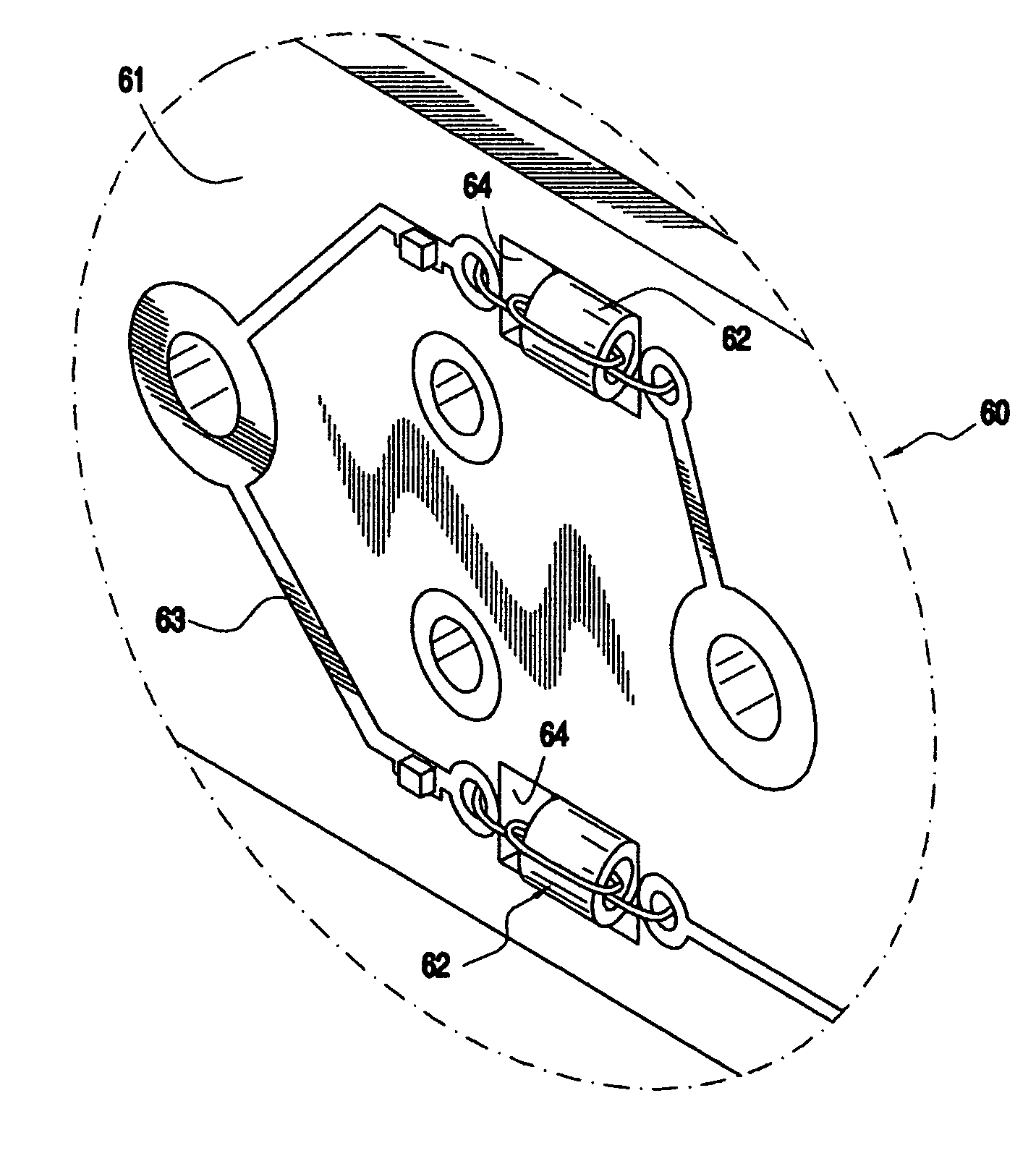
Figure 1 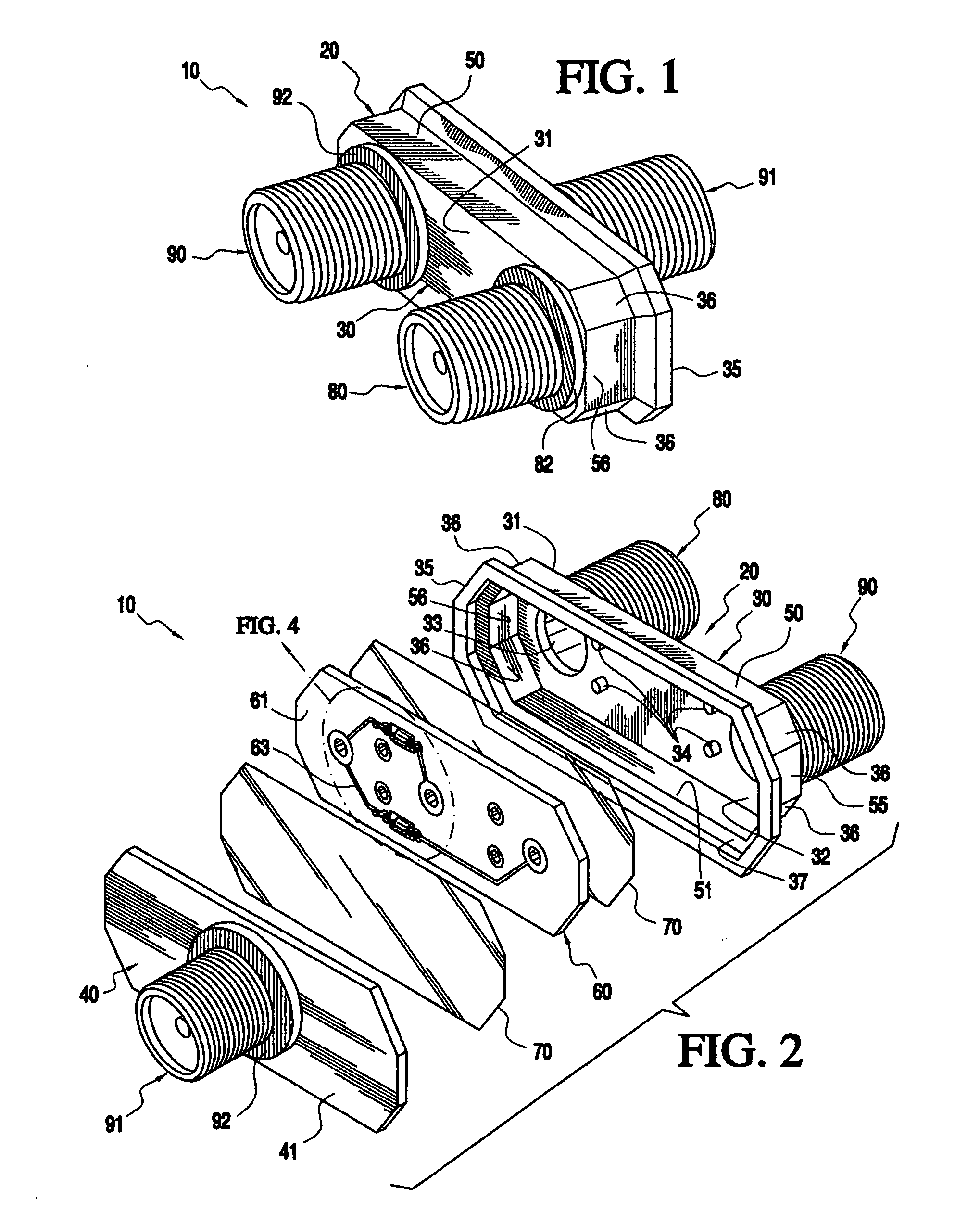
Figure 2 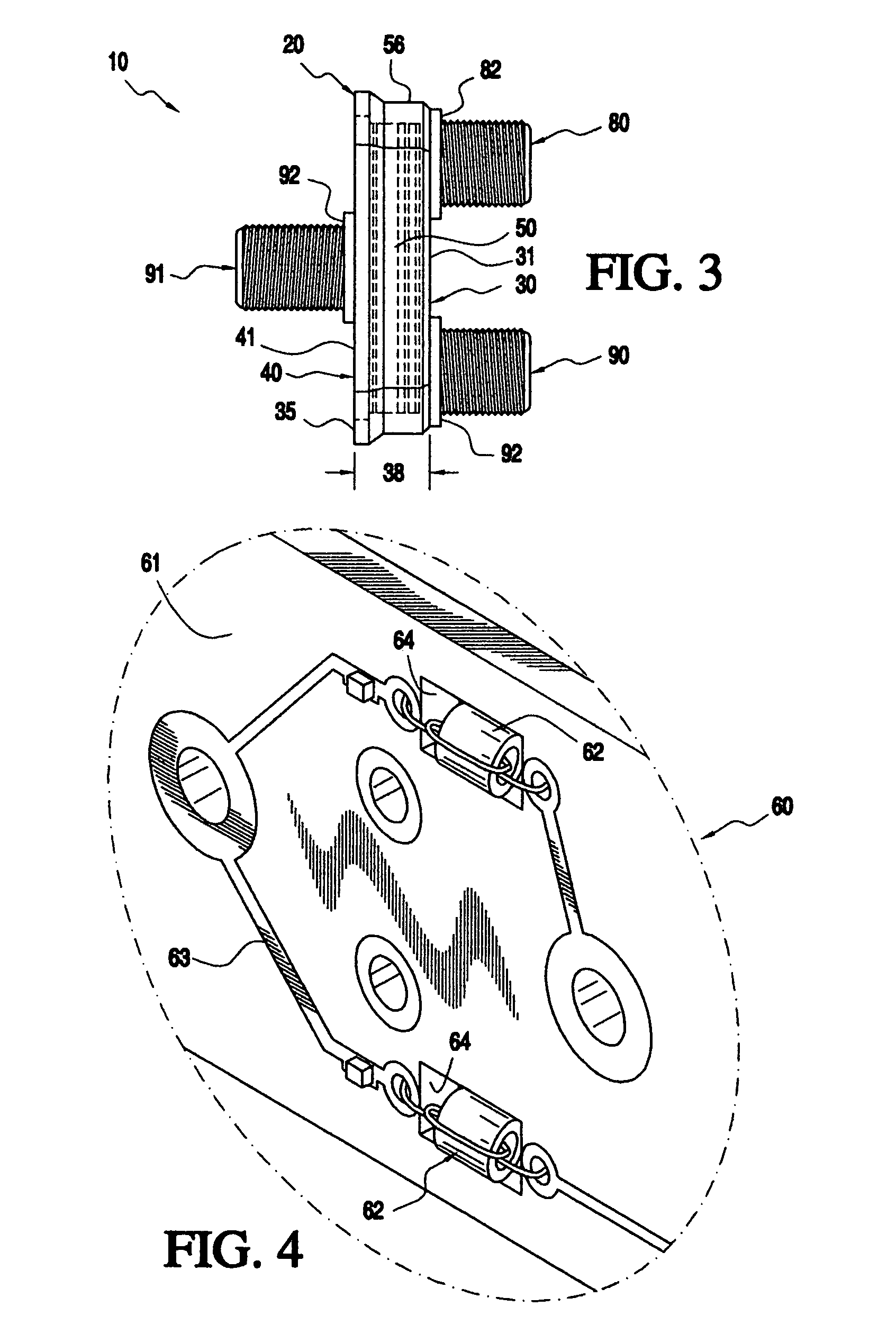
Figure 3
Abstract
Description
CROSS REFERENCE TO RELATED APPLICATION
[0001] This nonprovisional application claims the benefit of Provisional Application No.: 60 / 690,208, filed on Jun. 13, 2005, which is incorporated herein by reference in its entirety and to which priority is claimed.BACKGROUND OF THE INVENTION
[0002] 1. Field of Invention
[0003] The present invention is related to the field of electronic signal splitter and combiners, in particular radio frequency splitters.
[0004] 2. Description of Related Art
[0005] Televisions and computers and other similar devices receive electronic signals from a variety of sources. The primary means to deliver electronic signals is through cables, predominately coaxial cables, which carry a signal from sources such as satellite receivers, land-line cable or roof mounted antennas. Many homes, apartments and offices today have multiple televisions and computers that used these signals. It is not the intent of this invention to discuss how an electronic signal is delivered...
Examples
Embodiment Construction
[0039] The present invention is an electronic signal continuity device 10, wherein the device 10 in particular is an electronic signal splitter. It should be appreciated that in other various exemplary embodiments the device could include other electronic continuity devices such as, but not limited to, directional couplers, multi-switches, and amplifiers for example.
[0040] The present invention incorporates a signal splitter / combiner with a single input connector and multiple “n” output connectors. The present invention utilizes current electronic signal splitting technology, such as but not limited to the basic “Wilkinson” technique on a printed circuit board or PCB. When the present invention is used as signal combiner, the multiple “n” output connectors become multiple “n” input connectors and the single input connector becomes the single output connector. Throughout this detailed description, only the aspects of the splitter will be discussed, with the understanding that when t...