
Method of obtaining correction value of optical sensor and recording apparatus
a technology applied in the field of obtaining the correction value of optical sensors and recording equipment, can solve the problem that the recording head cannot adhere to an appropriate position during the actual recording operation, and achieve the effect of accurate position
Patent Information
- Authority / Receiving Office
- US · United States
- Patent Type
- Applications(United States)
- Current Assignee / Owner
- Publication Date
- 2007-03-08
- Estimated Expiration
- Not applicable · inactive patent
Smart Images
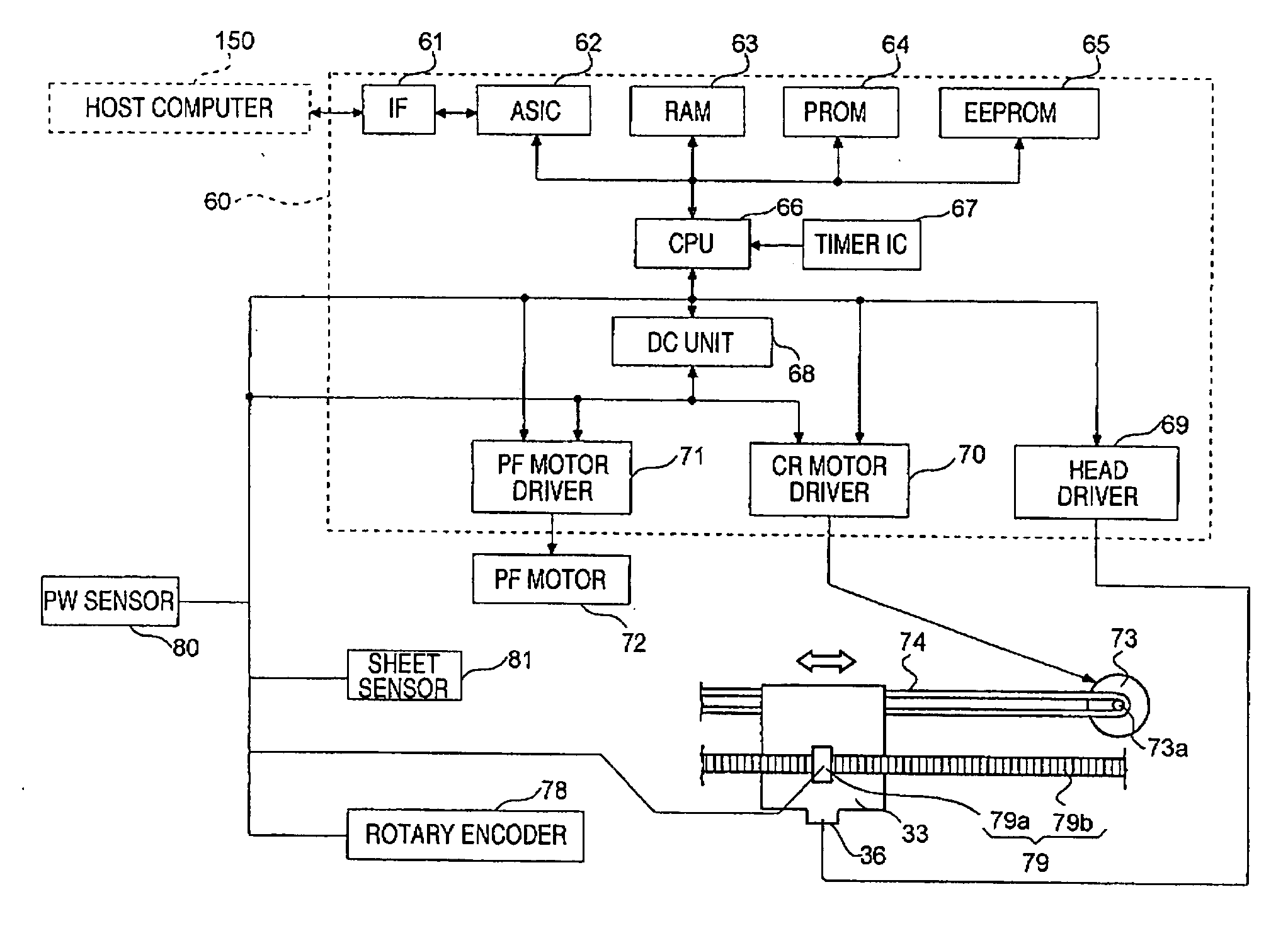
Figure 1 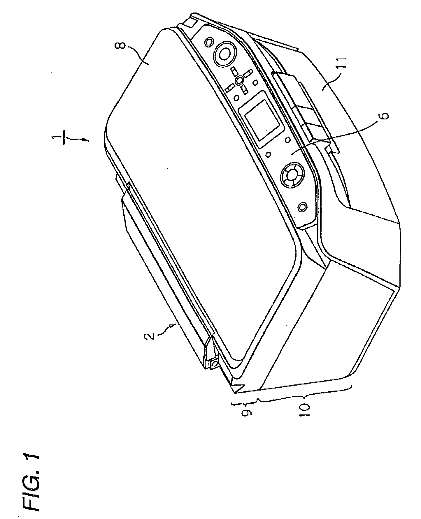
Figure 2 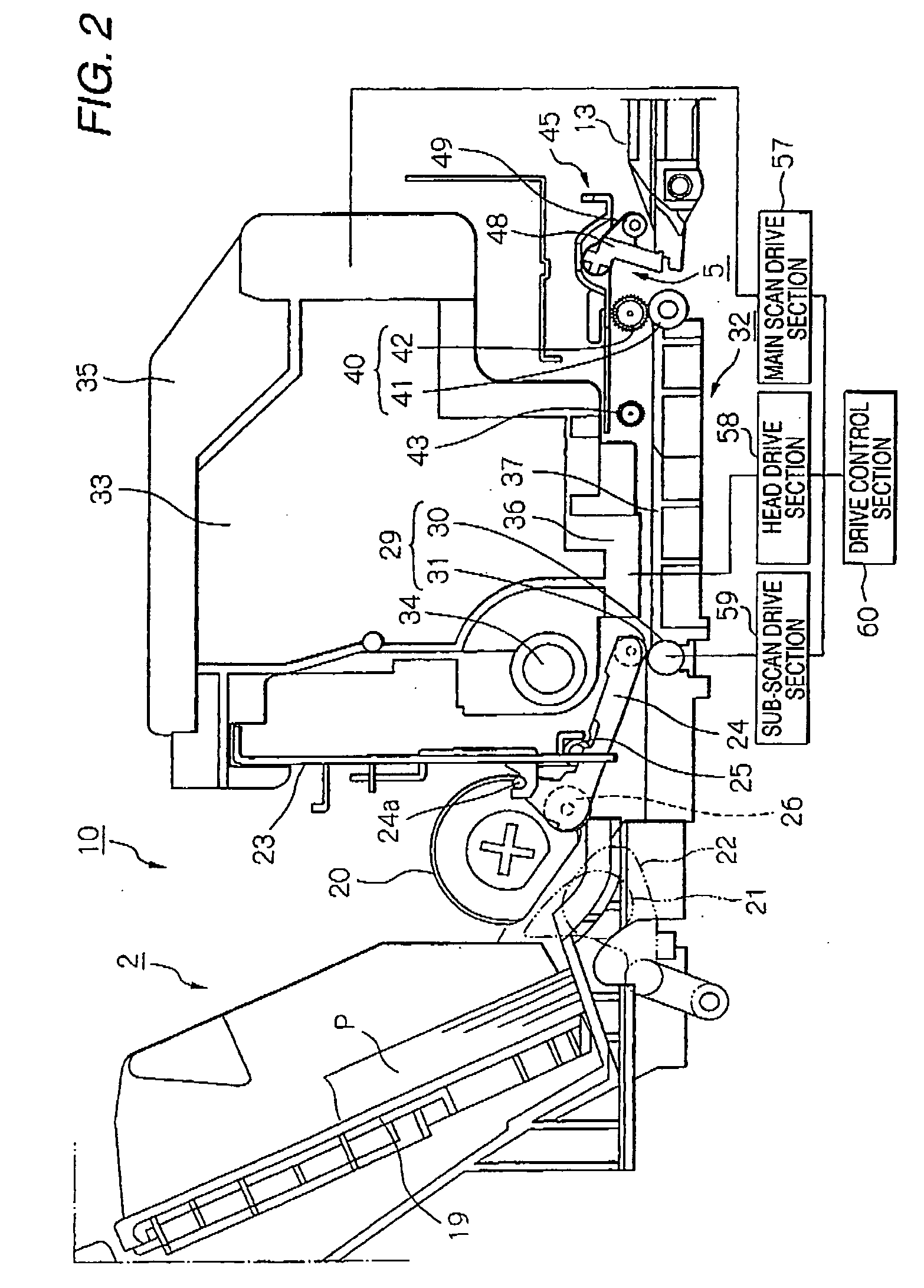
Figure 3
Abstract
Description
BACKGROUND OF THE INVENTION
[0001] The present invention relates to a method for obtaining a correction value of an optical sensor used for detecting an edge of a recording medium, as well as to a recording apparatus.
[0002] In a recording apparatus typified by a facsimile, a printer, or the like, a carriage having a recording head used for performing a recording on a recording medium is sometimes equipped with an optical sensor capable of detecting optical reflectance of a transport path (converting the intensity of reflected light into a current value) and disposed at a position opposing the transport path of the recording medium.
[0003] For instance, as described in JP-A-2004-243741, this optical sensor is used for detecting the position of an end (edge) of a recording medium in an inkjet printer. Specifically, the intensity of reflected light differs between a state where the recording medium is present and a state where the recording medium is not present Accordingly, the posit...
Examples
first embodiment
[0085] [First Embodiment]
[0086] Subsequently, by reference to FIGS. 5 to 12, a first embodiment of the present invention will be described. FIG. 5 is a plan view (a view of the carriage 33 when viewed from above) showing a positional relationship among the leading edge of the sheet P, the recording head 36, and the PW sensor 80. FIG. 6 is a plan view (a view of the carriage 33 when viewed from above) showing a positional relationship among the trailing edge of the sheet P, the recording head 36, and the PW sensor 80. FIG. 7 is a view showing a direction in which the edge of the sheet is sensed by the PW sensor 80. FIG. 8 is a view showing that a correction value obtainment pattern is formed along the leading edge of the sheet. FIG. 9 is a view showing that the correction value obtainment pattern is formed along a side edge of the sheet. FIGS. 10 through 12 are flowcharts showing procedures employed at the time of formation of the correction value obtainment pattern.
[0087] In FIGS. ...
second embodiment
[0121] [Second Embodiment]
[0122] Subsequently, a second embodiment will be described by reference to FIGS. 13 to 19. FIG. 13 is a view showing that the correction value obtainment pattern 200 is formed along the leading edge of the sheet; FIG. 14 is a view showing that the correction value obtainment pattern 200 is formed along the trailing edge of the sheet; and FIGS. 15 to 19 are flowcharts showing procedures for forming the correction value obtainment pattern along the upper and trailing edges and the right and left sides of the sheet P.
[0123] The correction value obtainment pattern 200 shown in FIG. 13 is analogous to that shown in FIG. 8, but differs from the first embodiment in terms of a method for detecting the leading edge of the sheet.
[0124] Specifically, when the leading edge of the sheet P has an inclination angle θ with respect to the line parallel to the direction “x” as shown in FIG. 13, the detected position of the leading edge additionally includes an error attrib...