
Compact reflector fluorescent lamp with good heat dispersion
a fluorescent lamp and reflector technology, applied in the field of fluorescent lamps, can solve the problems of prone to damage to the reflection shield of such energy saving lamps, affecting the lifespan of circuit boards mounted inside energy saving lamps, etc., and achieve the effect of heat dissipation and better configuration
Patent Information
- Authority / Receiving Office
- US · United States
- Patent Type
- Applications(United States)
- Current Assignee / Owner
- Publication Date
- 2008-08-14
- Estimated Expiration
- Not applicable · inactive patent
Smart Images
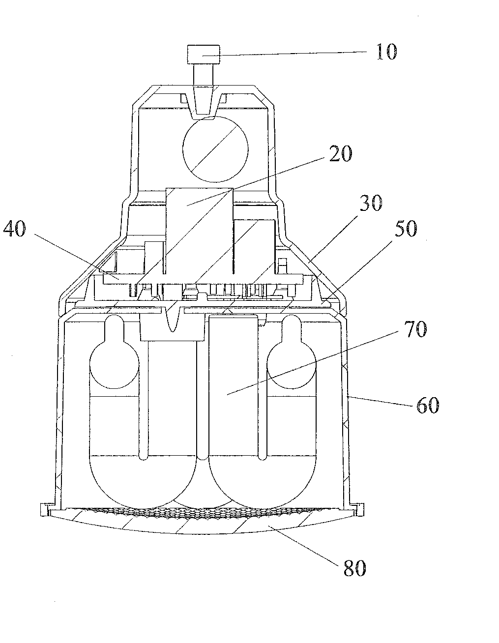
Figure 1 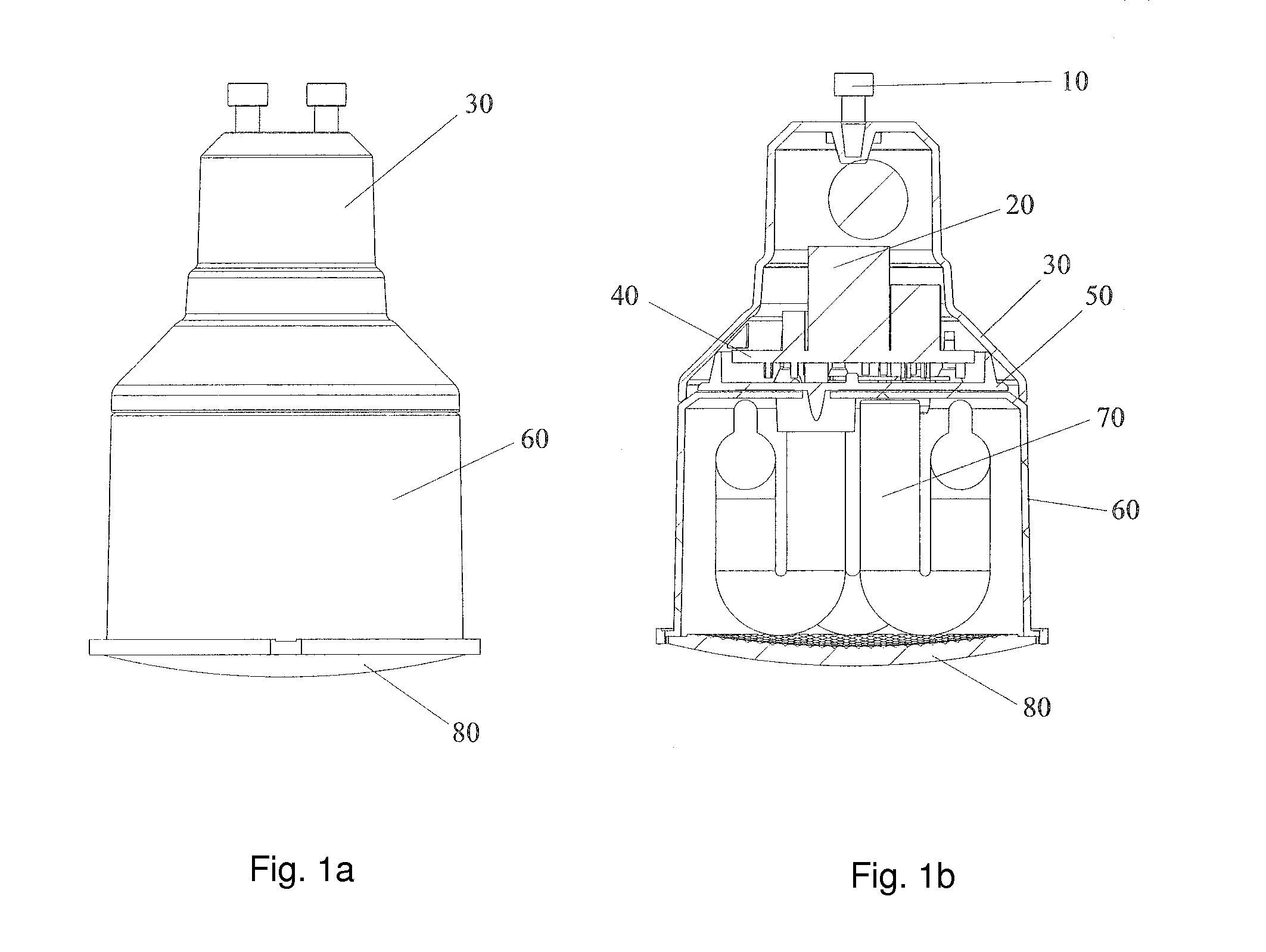
Figure 2 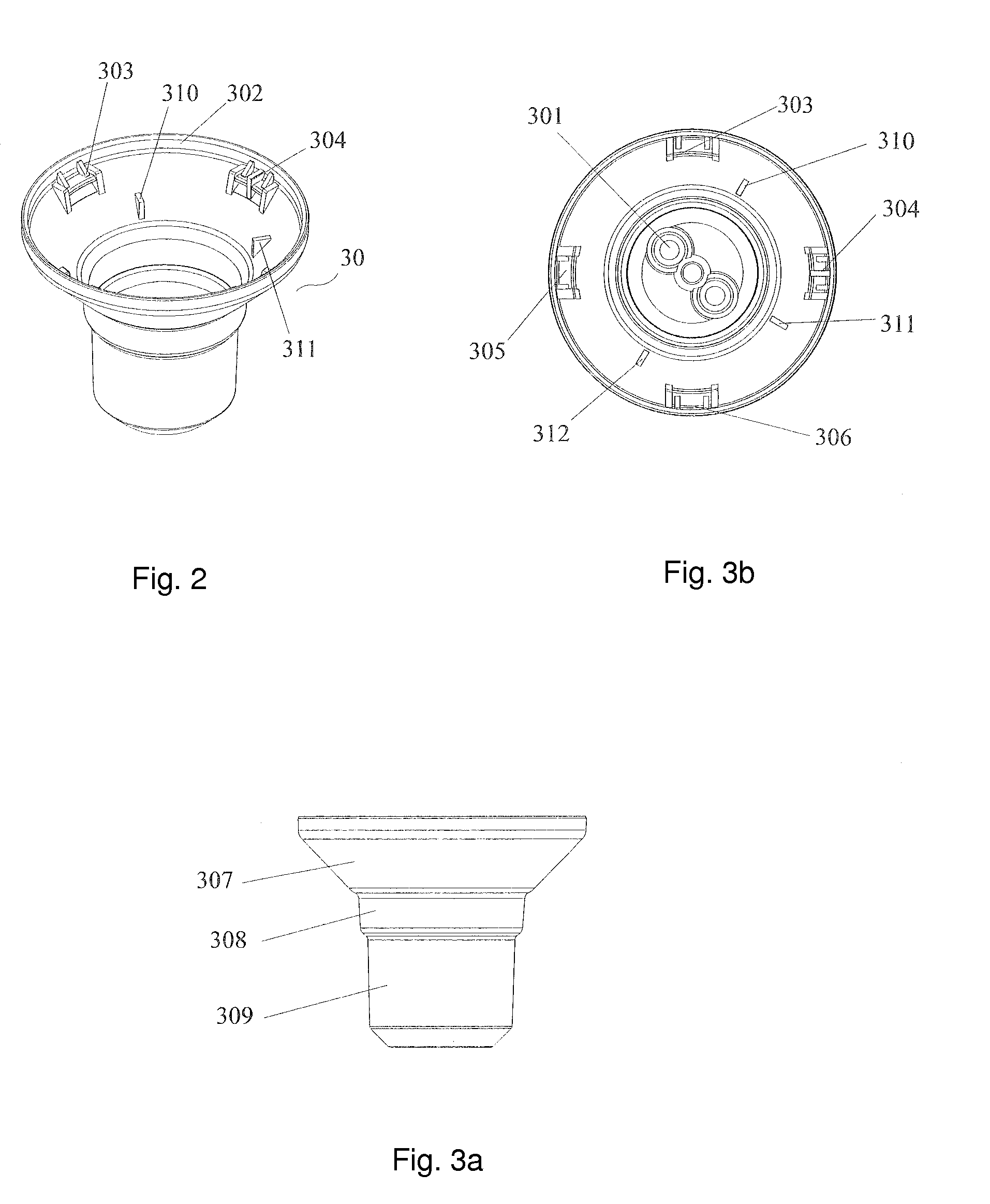
Figure 3
Abstract
Description
TECHNICAL FIELD
[0001] The present invention relates to a fluorescent lamp, and more particularly to a compact reflector fluorescent lamp unit with good heat dispersion.BACKGROUND OF THE INVENTION
[0002] At the present day, an existing reflector fluorescent lamp unit is configured by adopting an energy saving lamp tube around which a conical glass reflection shield is mounted. Such a unit makes use of the convergent action of the glass reflection shield to achieve the object of orientated illumination. Though the unit can solve the problem of poor optical efficiency of a conventional energy saving lamp, it suffers from the poor heat dispersion as the reflection shield generally made of glass and the electronic ballast are both mounted in the housing of the energy saving lamp such that the radiation heat of the lamp tube cannot sufficiently emitted to outside, which seriously endangers the lifespan of the circuit board mounted inside the energy saving lamp, while the reflection shield of...
Examples
Embodiment Construction
[0028]Please refer to FIGS. 1a and 1b, which illustrates a preferred embodiment of a compact reflector fluorescent lamp unit with good heat dispersion of the present invention, comprising a lamp cap 10, an electronic ballast assembly 20, a housing 30, a circuit board 40, an intermediate plate 50, a reflection cup 60, a lamp tube 70, and a transparent plate 80; wherein the lamp cap 10 might adopts a two-pin type lamp cap and / or a screwed type lamp cap; in the present embodiment, a two-pin type lamp cap having two conducting contact protrusions such as a GU10 lamp cap is used as the lamp cap.
[0029]The electronic ballast assembly 20 is a conventional ballast which can be used with lamp tubes of various standards and model numbers. The input end of the electronic ballast assembly 20 might be connected to the conducting contact protrusions of the lamp cap 10 via conductors while its output end can be connected to the lamp tube 70.
[0030]Please refer to FIGS. 2, 3a and 3b, wherein the hous...