
Low-Noise, High-Speed, High Precision and High-Thrust Flux Reversal Motor for Linear or Rotary Motion System
Patent Information
- Authority / Receiving Office
- US · United States
- Current Assignee / Owner
- Publication Date
- 2009-01-08
Smart Images
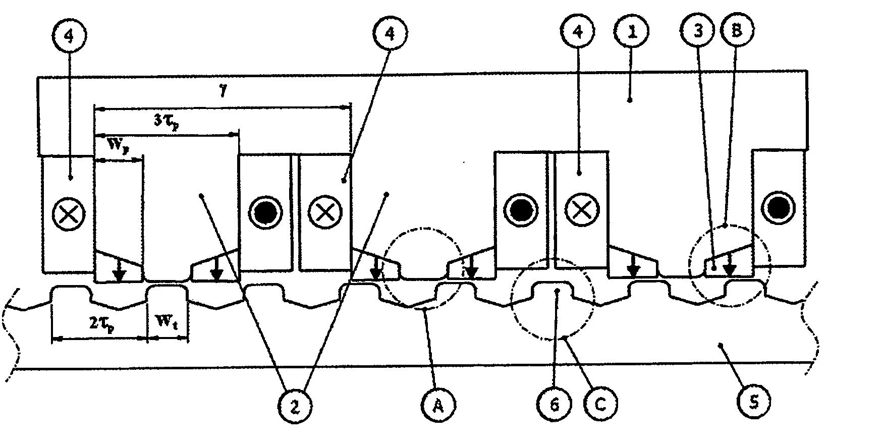
Figure 1 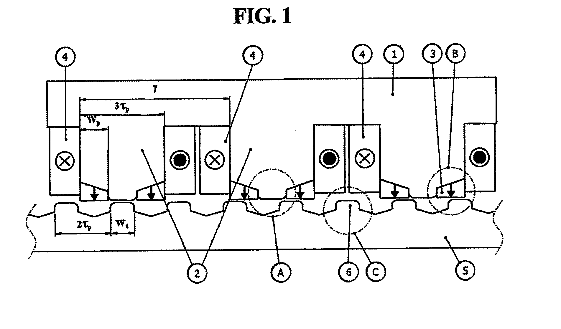
Figure 2 
Figure 3
Abstract
Description
BACKGROUND OF THE INVENTION
[0001] 1. Field of the Invention
[0002] The present invention relates generally to a flux reversal motor and, more particularly, to a linear motor, which can decrease the number of permanent magnets that are used, can facilitate magnetization using permanent magnets having the same polarities, can move at high speed because thrust is increased, and can realize low noise / low vibration and high precision position control by decreasing the pulsation of thrust and normal force, and to a rotary motor, which is based on the concept of the linear motor, and which can prevent the degradation of the permanent magnets from occurring because the permanent magnets are provided in a rotor, can prevent scattering from occurring because the permanent magnets are provided in a stator, and can be effectively manufactured by applying divided iron cores to a stator or rotor.
[0003] 2. Description of the Related Art
[0004] A conventional linear motor representatively includes a perm...
Examples
Embodiment Construction
[0048]Preferred embodiments of the present invention are described in detail below with reference to the accompanying drawings and details described in the accompanying drawings, but the present invention is not limited to the embodiment, and is not to be defined by the embodiments. The same reference numerals, which are used throughout the different drawings, designate the same or similar components.
[0049]FIG. 1 is a view illustrating the mover and stator of a linear motor according to an embodiment of the present invention. Referring to FIG. 1, the mover of the linear motor according to the embodiment of the present invention includes a mover core 1, mover teeth 2, permanent magnets 3, and mover phase coils 4. The stator of the linear motor according to the embodiment of the present invention includes a stator core 5 and stator teeth 6.
[0050]When an appropriate amount of current is applied to the mover phase coils 4, which are formed by winding the coil around the mover teeth 2, a...