
System and method for flow cytometry
a flow cytometry and flow cytometry technology, applied in the field of optical devices, can solve the problems of increasing the complexity and cost of such cytometry systems, limiting the use of laboratory laboratories in major metropolitan areas, and the relatively high complexity and cost of conventional flow cytometry techniques, so as to reduce light loss by reflection, improve the efficiency of directing light, and improve the effect of directing ligh
Patent Information
- Authority / Receiving Office
- US · United States
- Current Assignee / Owner
- Publication Date
- 2009-01-29
- Estimated Expiration
- Not applicable · inactive patent
Smart Images
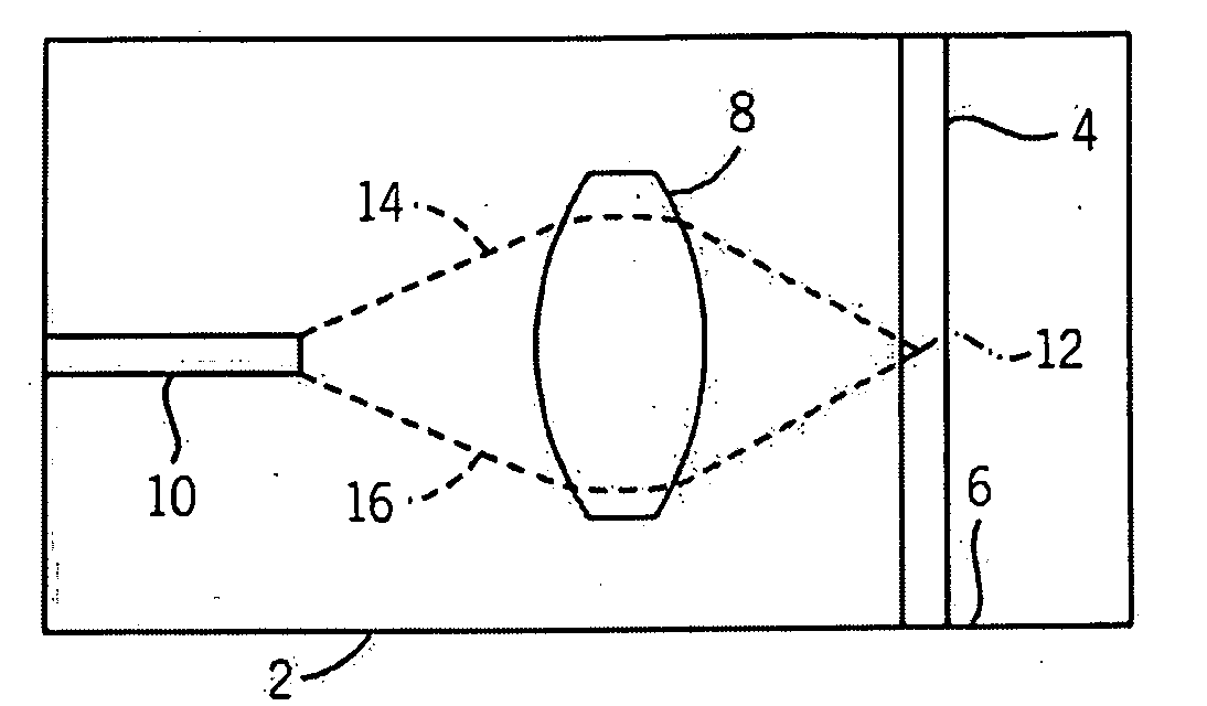
Figure 1 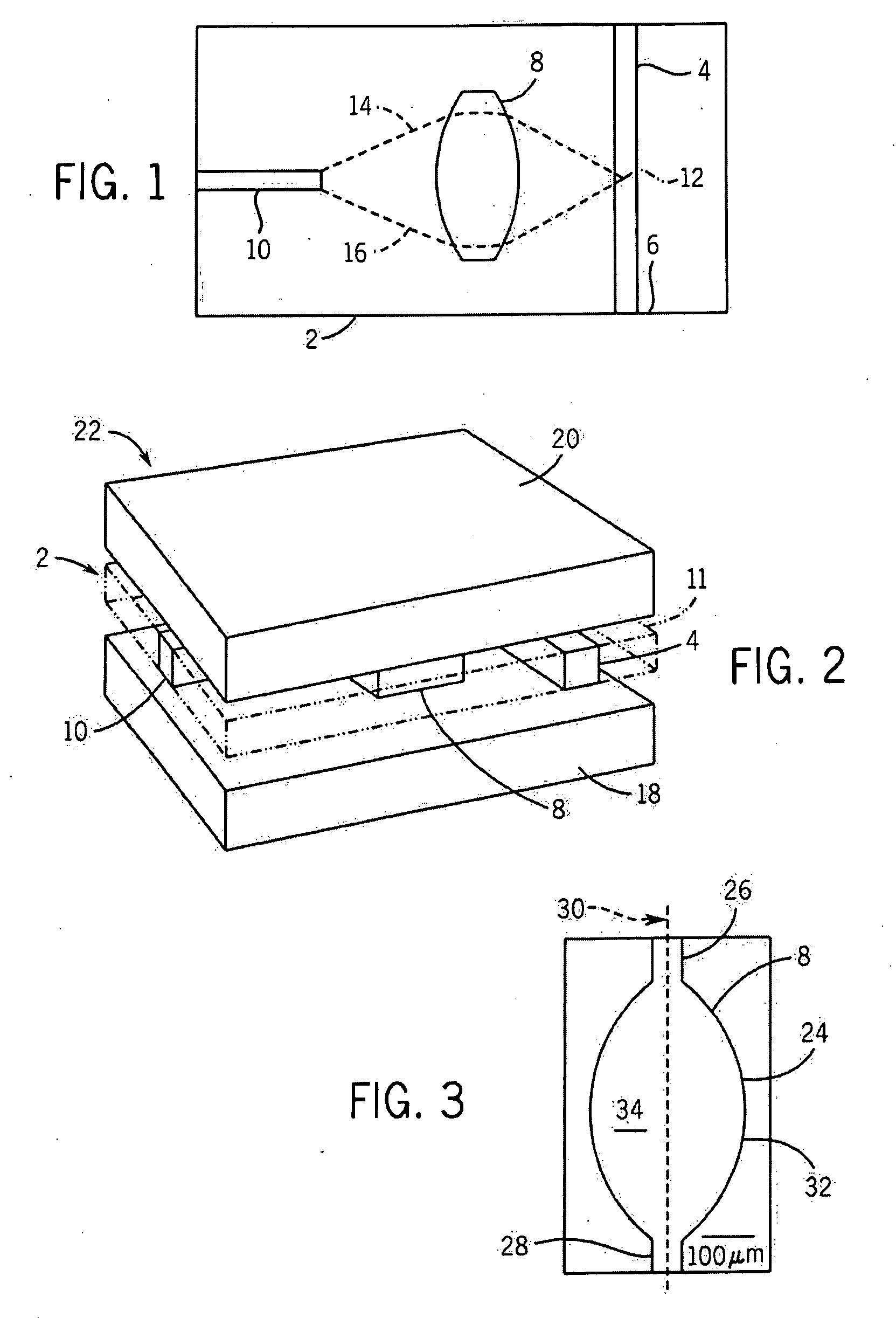
Figure 2 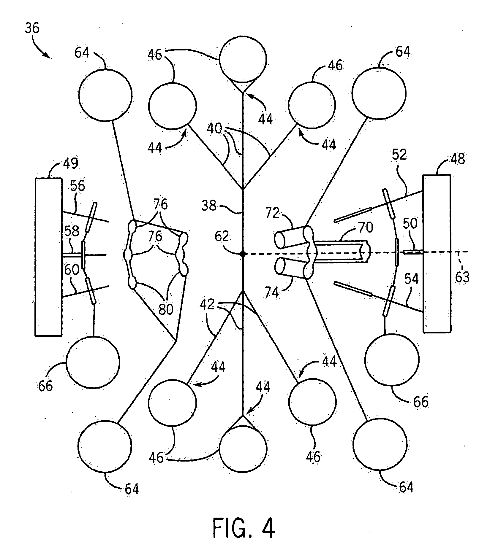
Figure 3
Abstract
Description
CROSS-REFERENCE TO RELATED APPLICATIONS
[0001] This application claims the benefit of U.S. provisional patent application No. 60 / 917,848, entitled “Light Conveying Device” filed on May 14, 2007, and further claims the benefit of U.S. provisional patent application No. 61 / 068,198, entitled “System and Method for Flow Cytometry” filed on Mar. 5, 2008, and both of the aforementioned U.S. provisional patent applications are hereby incorporated by reference herein.STATEMENT REGARDING FEDERALLY SPONSORED RESEARCH OR DEVELOPMENT
[0002] This invention was made with United States Government support awarded by the following agency: Air Force Office of Scientific Research (AFOSR) Grant No. F49620-02-1-0288. The United States Government has certain rights in this invention.FIELD OF THE INVENTION
[0003] The present invention relates to optical devices and, more particularly, relates to devices for conveying and / or sensing light, for example, devices that convey and sense light emissions from cells, pa...
Examples
Embodiment Construction
[0024]A top plan view of components 2 of an exemplary microfluidic flow cytometer are shown in schematic form. As shown, the cytometer components 2 include a microfluidic channel 4 that is capable of conducting fluids that can contain various biological materials such as blood cells or other types of cells, particles or possibly other types of materials. Fluid flow (as directed by a pump, gravity, or some other force) can proceed through the microfluidic channel 4 along a direction represented by an arrow 6, although the fluid can be directed in either direction depending upon the embodiment. Spaced apart to the side of the microfluidic channel 4 is a microfluidic lens 8, and additionally spaced apart from the lens is a waveguide 10. Thus, the lens 8 is between the microfluidic channel 4 and the waveguide 10, with the waveguide 10 extending away from the lens in a direction that also extends away from the channel.
[0025]As shown, the waveguide 10 in the present embodiment is orientat...