
Battery manufacturing method and apparatus
a battery manufacturing method and battery technology, applied in the direction of cell components, final product manufacturing, sustainable manufacturing/processing, etc., can solve the problems of reducing processing accuracy and difficulty in accurately positioning the electrode sheet, so as to minimize the lowering of the processing accuracy of the electrode sheet and minimize the undesired thickness change of the electrode sheet
Patent Information
- Authority / Receiving Office
- US · United States
- Patent Type
- Applications(United States)
- Current Assignee / Owner
- Publication Date
- 2009-04-23
- Estimated Expiration
- Not applicable · inactive patent
Smart Images
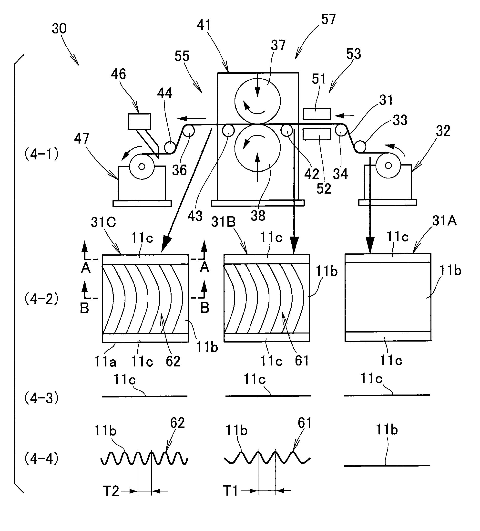
Figure 1 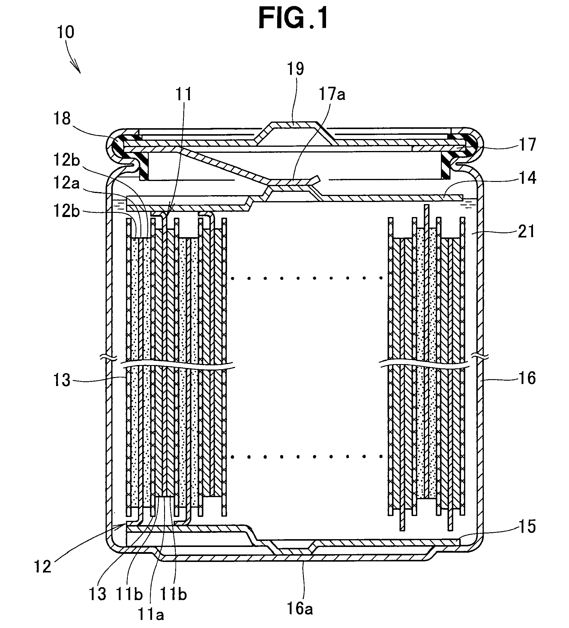
Figure 2 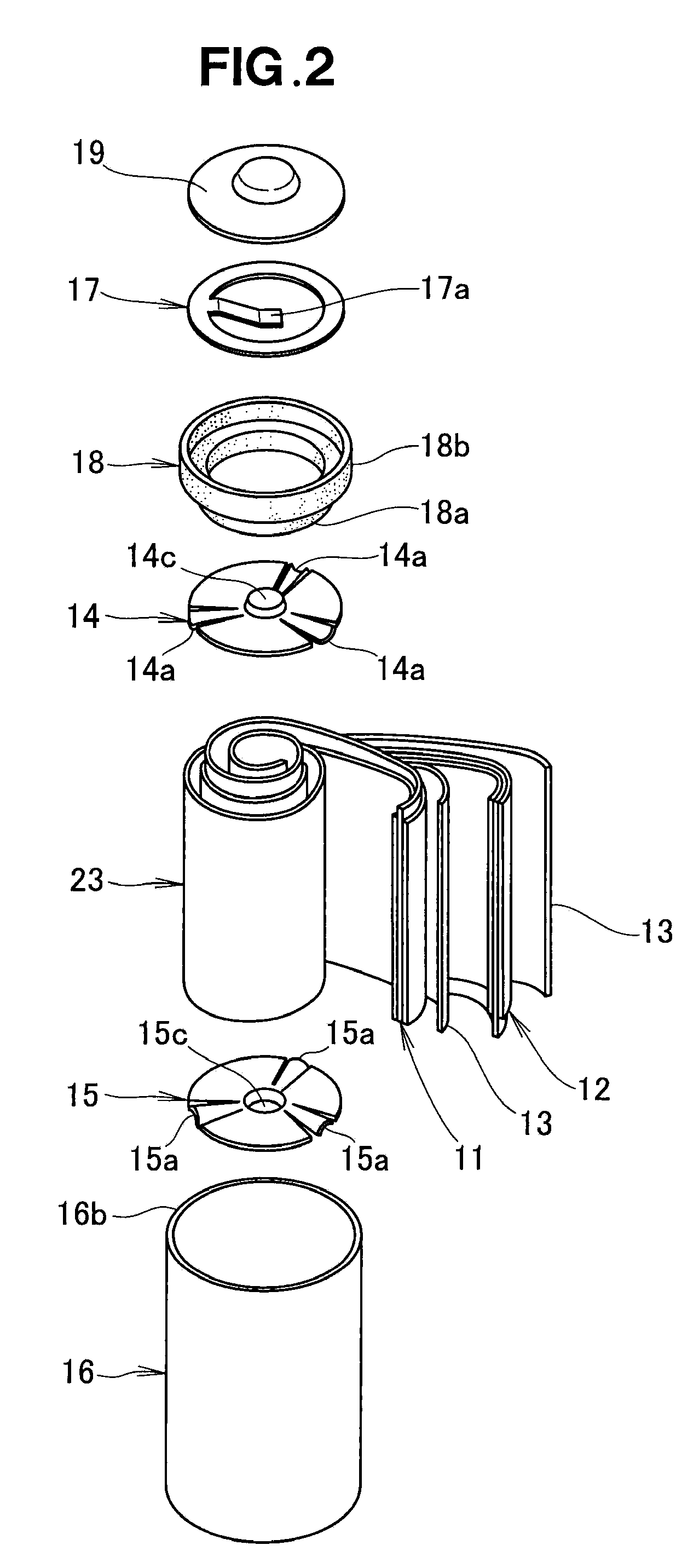
Figure 3
Abstract
Description
FIELD OF THE INVENTION
[0001] The present invention relates to an improvement in a battery manufacturing method and apparatus.BACKGROUND OF THE INVENTION
[0002] There have been known batteries including a roll-shaped electrode assembly formed by winding sheet-shaped positive and negative electrodes into a roll shape together with a separator. In manufacturing positive and negative electrodes of these conventionally-known batteries, the positive and negative electrodes would be undesirably deformed due to a difference in extension (or elongation) between a portion coated with an electrode active material and other portions not coated with the electrode active material, as detailed below with reference to FIG. 14 hereof.
[0003] FIG. 14 is a view explanatory of a conventionally-known battery manufacturing method. Namely, an electrode sheet 203 having a coated portion 201 coated with an electrode active material 200 and non-coated portions 202 not coated with the electrode active material 200...
Examples
Embodiment Construction
[0033]Reference is now made to FIG. 1 showing in section a battery manufactured in accordance with the present invention. The battery 10 includes: positive and negative sheet electrodes 11 and 12 each having its opposite surfaces coated with an electrode active material; separators 13 disposed between the positive and negative sheet electrodes 11 and 12 etc.; a current collector 14 held in contact with an upper end portion (i.e., non-active-material-coated portion) of the positive sheet electrode 11; a current collector 15 held in contact with a lower end portion (i.e., non-active-material-coated portion) of the negative sheet electrode 12; a conductive case 16 having accommodated therein the positive and negative sheet electrodes 11 and 12, separators 13 and disk-shaped current collector 14 and 15; a conductive plate 17 pressing the positive and negative sheet electrodes 11 and 12, separators 13 and current collector 14 and 15 against the bottom of the case 16; a lid 19 swaged, via...