
Electric Motor and Method for Manufacturing an Electric Motor
Patent Information
- Authority / Receiving Office
- US · United States
- Current Assignee / Owner
- Publication Date
- 2009-05-28
Smart Images
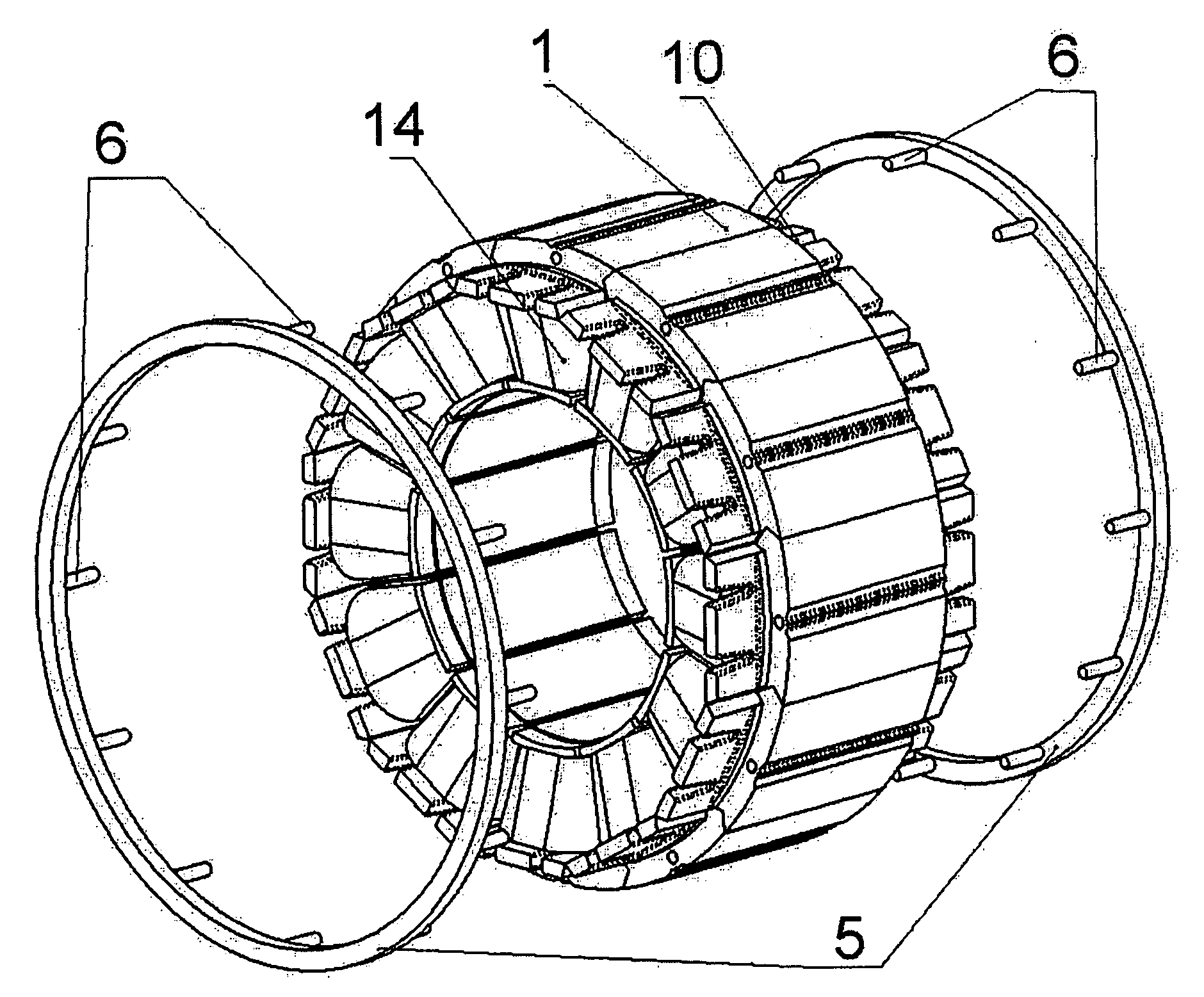
Figure 1 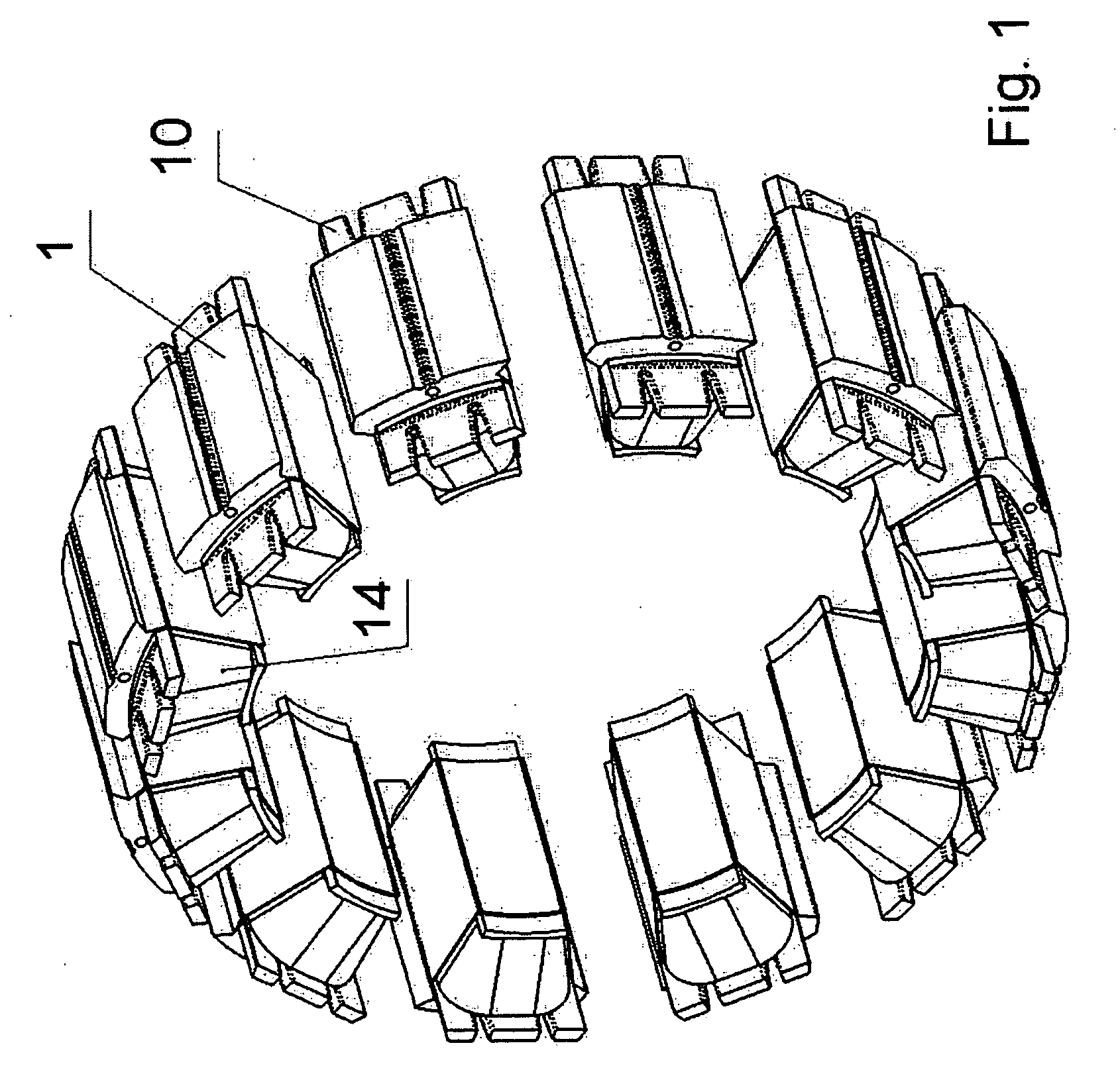
Figure 2 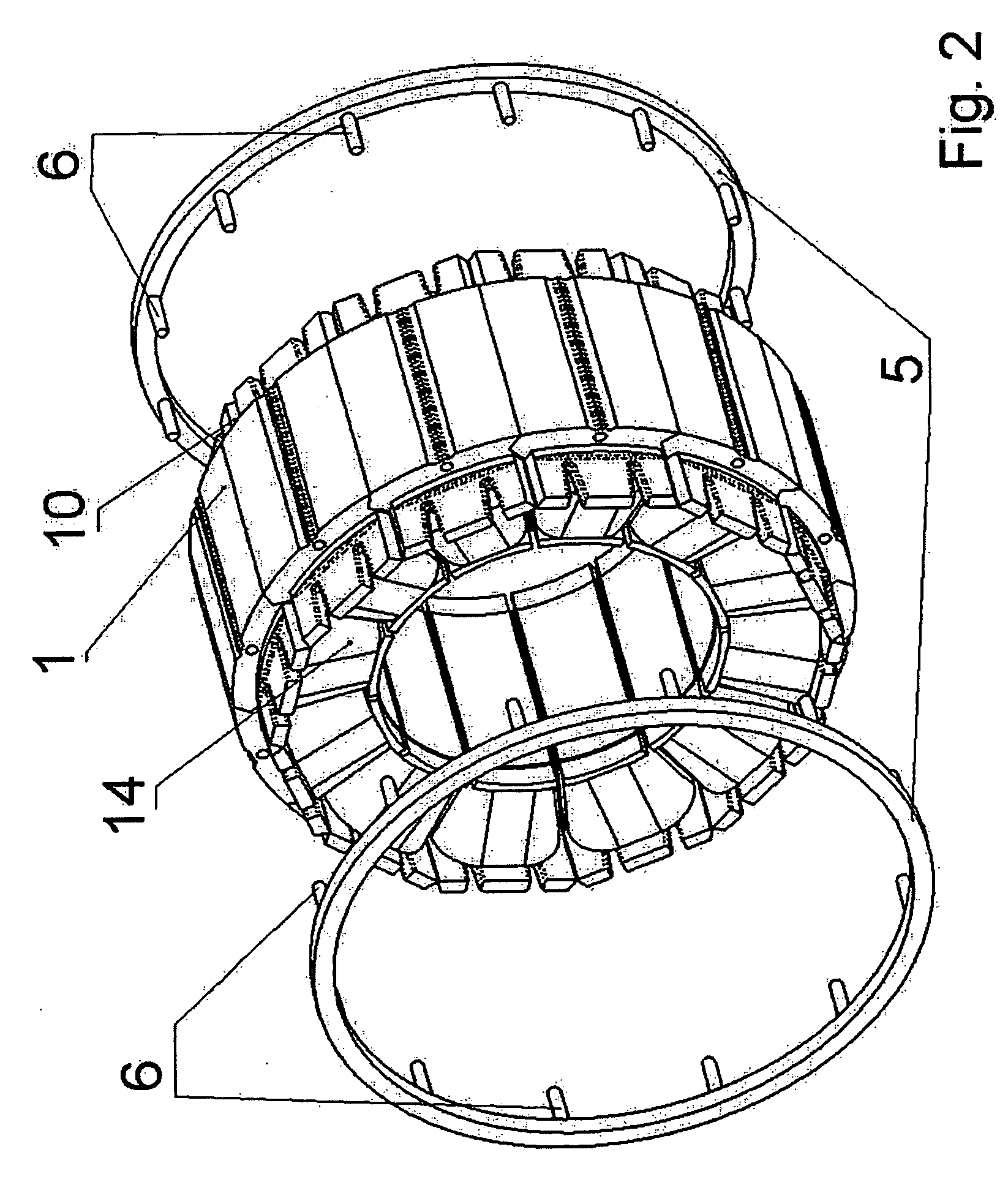
Figure 3
Abstract
Description
FIELD OF THE INVENTION
[0001] The present invention relates to an electric motor and a method for manufacturing an electric motor.BACKGROUND INFORMATION
[0002] European Published Patent Application No. 1 322 021 describes a stator in which the teeth of the stator are axially inserted into a hollow cylindrical annular body. Caps, having electrical plug connections, are plugged onto both ends. The large mass and thus costly manufacture of the motor is a disadvantage.
[0003] U.S. Pat. No. 6,226,856 also describes a stator in which the teeth of the stator are inserted axially into one another.
[0004] U.S. Pat. No. 6,359,355 describes a stator in which the segments are indeed brought together radially, but they are retained by a surrounding “circular pattern 28”.SUMMARY
[0005] Example embodiments of the present invention provide a device and a method by which the manufacture of an electric motor and an associated series may be simplified and by which the protection of the environment may be improv...
Examples
Embodiment Construction
[0034]The motor according to example embodiments of the present invention includes a stator made up at least of tooth segments.
[0035]FIGS. 4 through 11 show the manufacturing steps of the fully wound tooth segment in order.
[0036]FIGS. 1 through 3 show the assembly of the stator from the tooth segments.
[0037]In the following, the figures are explained in more detail in sequence.
[0038]FIG. 4 shows a tooth segment 1. It has a groove 4 and a tongue 3 and a projection 8 produced by the stamp-packing process. In addition, a hole is provided for inserting pegs 6.
[0039]FIG. 5 show the insulating paper 9 that is slid onto the tooth segment.
[0040]FIG. 6 shows tooth segment 1 having insulating paper 9 slid onto it.
[0041]FIG. 7 shows an end cap 10, which has grooves 12 for guiding wires and a coil support 11 for securing the winding and recesses as wire guides 13.
[0042]FIG. 8 shows a tooth segment having slid-on end caps 10.
[0043]FIG. 9 shows a tooth segment subsequently wound by winding 14.
[00...