
System for gas permeation testing
Patent Information
- Authority / Receiving Office
- US · United States
- Current Assignee / Owner
- Publication Date
- 2009-09-17
Smart Images
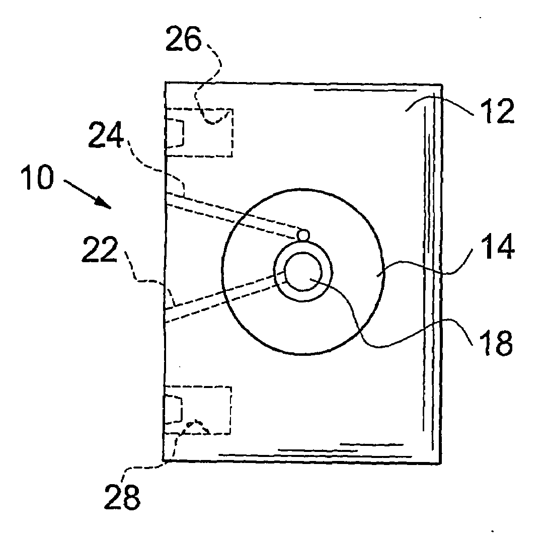
Figure 1 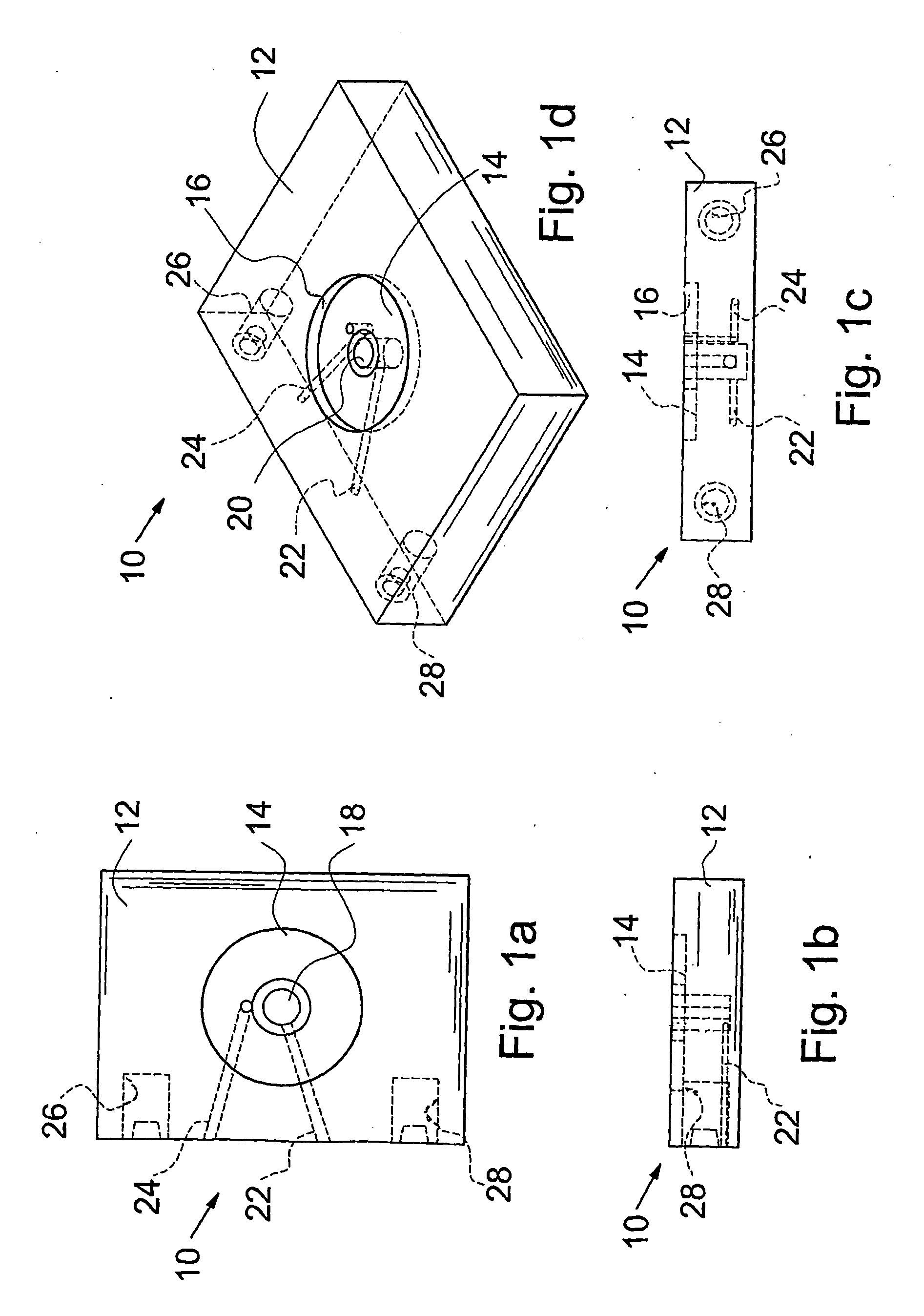
Figure 2 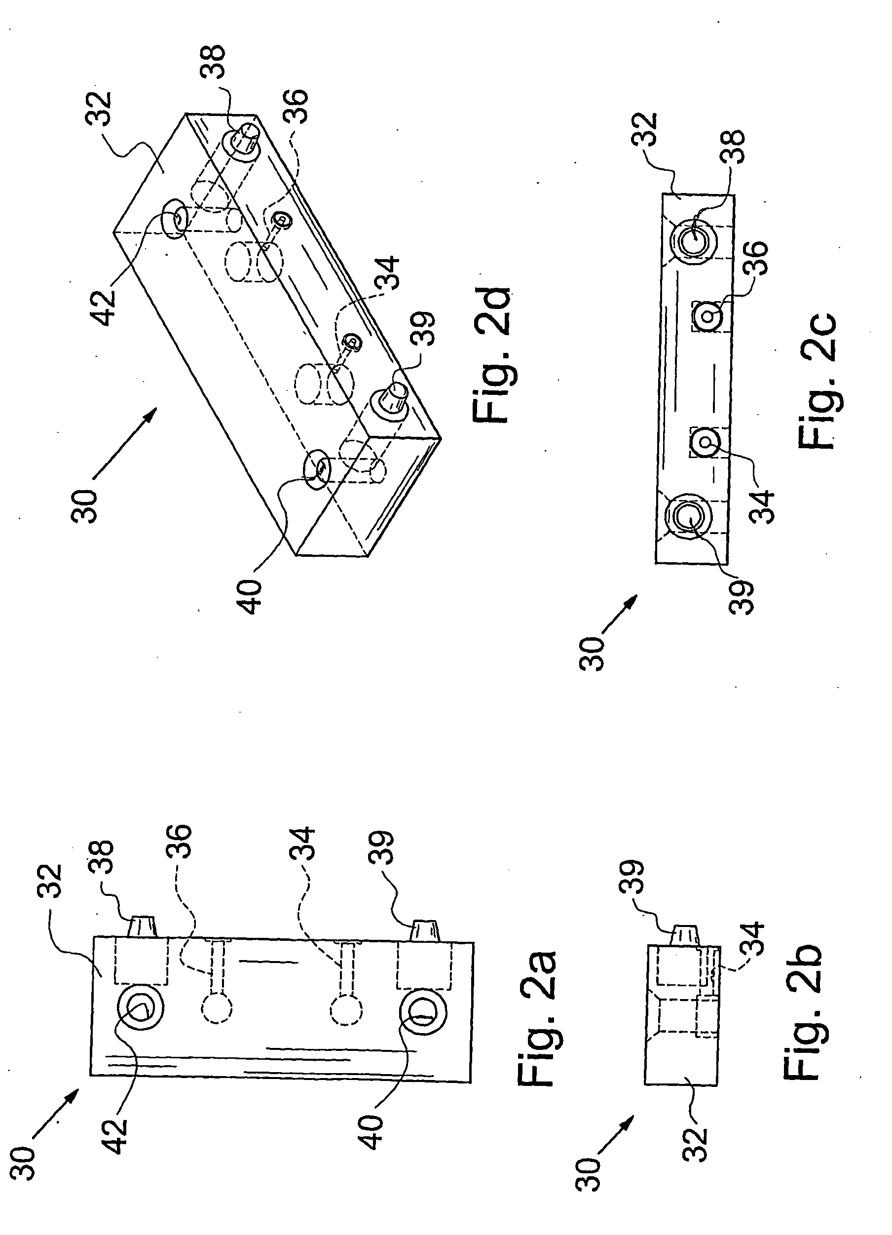
Figure 3
Abstract
Description
CROSS-REFERENCE TO RELATED APPLICATION
[0001] This application claims the benefit of U.S. Provisional Patent Application Ser. No. 60 / 722,278 filed on Sep. 30, 2005.BACKGROUND OF THE INVENTION
[0002] 1. Field of the Invention
[0003] The present invention relates to a container testing apparatus. More particularly, the present invention relates to a system for measuring gas permeation through plastic container walls.
[0004] 2. Description of the Prior Art
[0005] In the preservation of beverages which are liable to be affected by oxidation, there is a problem that the beverages are oxidized by a small amount of oxygen present in a container used for storage. Therefore, it is of paramount importance to ascertain the oxygen permeation characteristics of the plastic containers to be used for the beverage storage. In the prior art, the systems for testing oxygen permeation require that each time a container is placed on or removed from a system for gas permeation testing, the containers to be tested...
Examples
Embodiment Construction
[0022]Referring to the accompanying drawings, there is shown components of a system for mounting and connecting plastic material, such as used in containers for permeation testing which embody the features of the invention.
[0023]The system includes two main components; namely, moveable sample plates to which a container to be tested is affixed; and an associated manifold system.
[0024]A bushing shown in FIG. 1d is adapted to receive pins of an associated manifold 30 shown in FIG. 2d. The elements may be suitably affixed to the base plate 50 shown in FIGS. 3a, 3b, and 3c by threaded fasteners, for example.
[0025]The sample plate 10 comprises a main body 12 having an annular recess 14 for receiving the neck or finish of a plastic container to be tested. The recess 14 is defined by an annular shoulder 16. A coaxial recess 18 is formed centrally of the annular shoulder 16. The open end of the recess 18 is defined by an upstanding annular 20. A conduit 22 is formed in the main body 12 to p...