
Cryogenic storage container
a technology for cryogenic storage containers and storage containers, applied in the direction of containers, discharging methods, laboratory glassware, etc., can solve the problems of limited approach, waste of materials, time-consuming, etc., and achieve the effect of reducing the risk of cross-contamination, preventing spillage or contamination, and simplifying the handling and processing of biological specimens
Patent Information
- Authority / Receiving Office
- US · United States
- Patent Type
- Applications(United States)
- Current Assignee / Owner
- Publication Date
- 2009-10-15
- Estimated Expiration
- Not applicable · inactive patent
Smart Images
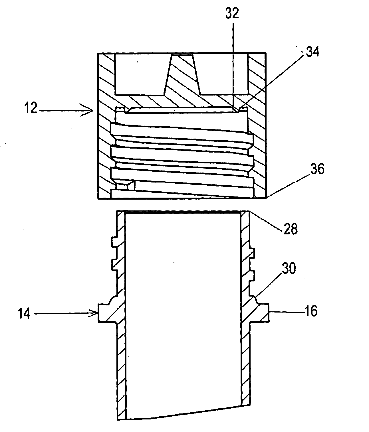
Figure 1 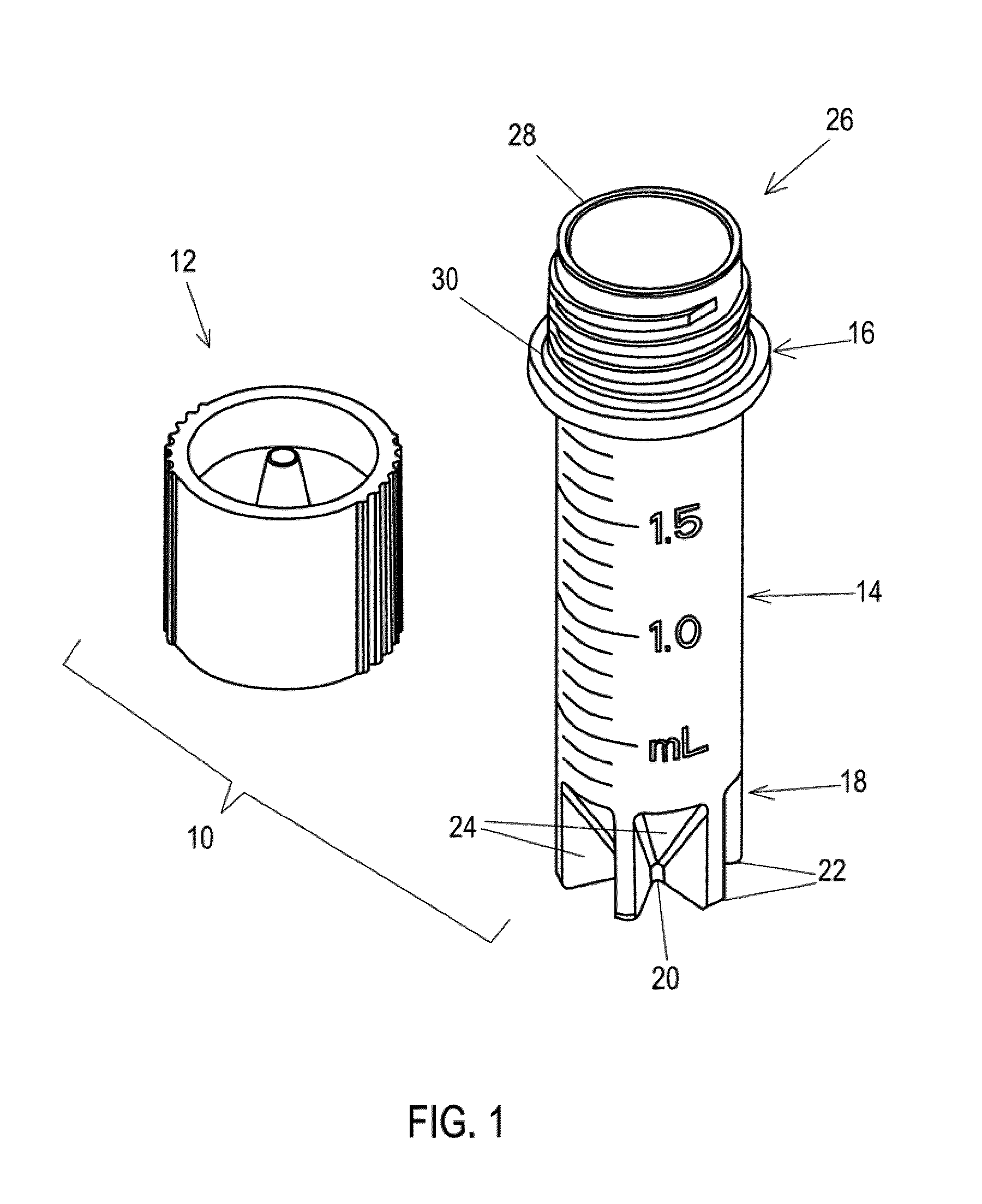
Figure 2 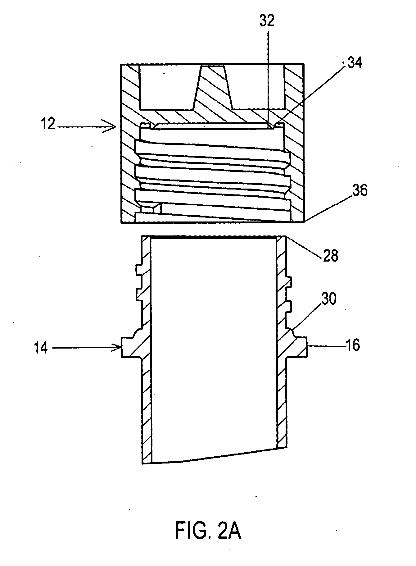
Figure 3
Abstract
Description
RELATED APPLICATIONS
[0001] This application claims the benefit of U.S. Provisional Patent Application Ser. Nos. 61 / 044,997, filed 15 Apr. 2008. The following U.S. Provisional Patent Applications are incorporated by reference into this present non provisional application, 61 / 046,706, filed 21 Apr. 2008 and 61 / 087,705, filed 10 Aug. 2008.BACKGROUND OF THE INVENTION
[0002] Biology, biochemistry immunology, and biotechnology often rely on the cryopreserved biological specimens for research, clinical and therapeutic developments. In the typical laboratory practice, the biological specimen is frozen in a cryovial and stored in a cryogenic freezer or dewar for a period of time. At the point of usage, the pre-cryopreserved specimen stored in the cryovial is taken from the freezer or dewar, and thawed in a warm water bath. After thawing, the solution is removed by a pipette and put into a centrifuge tube. The tube is then placed in a rotor and centrifuged to separate solid particles, such as ce...
Examples
Embodiment Construction
[0011]In one embodiment of the invention, shown in FIG. 1, a cryogenic storage container (10) includes a cap (12) and a vessel body (14). In the illustrated embodiment, a flange (16) is provided on vessel body (14) and a specialized bottom end (18) is formed in vessel body (14).
[0012]As shown in FIG. 1, the illustrated bottom end (18) is tapered so as to lead to a narrower tip (20). It is contemplated that tip (20) may be rounded or pointed. However, a plurality of fins (22) are positioned at bottom end (18) so as to provide, among other things, a stand that supports container (10) when it is positioned to stand on its bottom end (18) and better heat transfer capabilities during cooling and thawing steps in the cryopreservation process.
[0013]Between fins (22) at the bottom end (18) forms multiple vapor passages (24). Vapor passages (24) provide pathways to release vapor formed during cryopreservation. As such, it reduces vapor accumulation and vapor insulation layer at the bottom of...