
Intake manifolds for internal combustion engine
a technology for internal combustion engines and intake manifolds, which is applied in the direction of machines/engines, combustion air/fuel air treatment, and feed systems, etc. it can solve the problems of reducing the efficiency of the engine, the plenum is not sufficiently sized to create resonance chambers or vacuum cavities, and the synthetic distribution chamber further does not provide a large volume vacuum chamber. , to achieve the effect of improving performan
Patent Information
- Authority / Receiving Office
- US · United States
- Patent Type
- Applications(United States)
- Current Assignee / Owner
- Publication Date
- 2010-10-28
- Estimated Expiration
- Not applicable · inactive patent
Smart Images
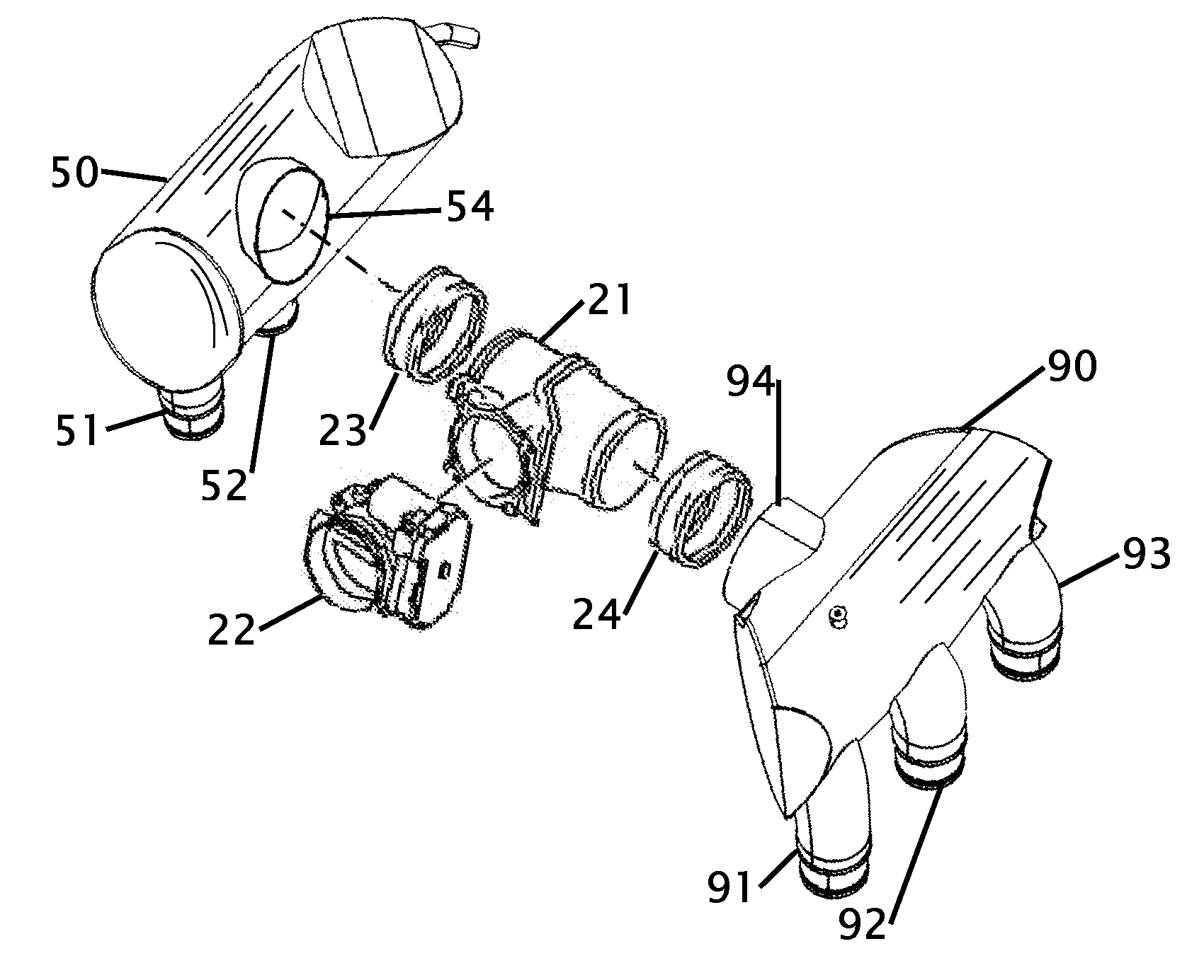
Figure 1 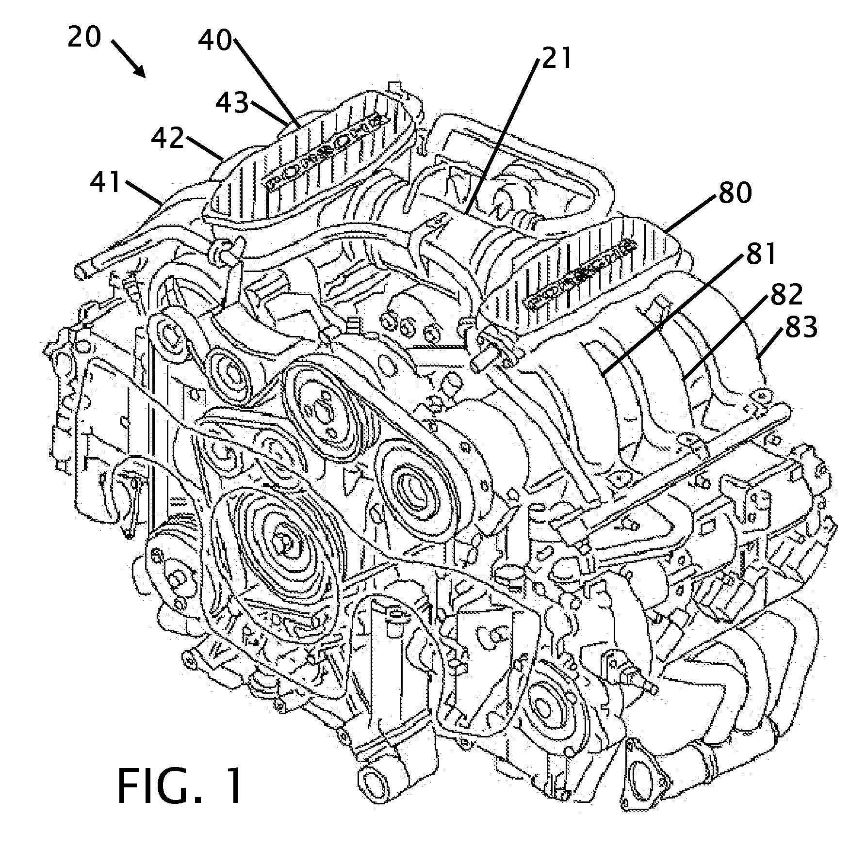
Figure 2 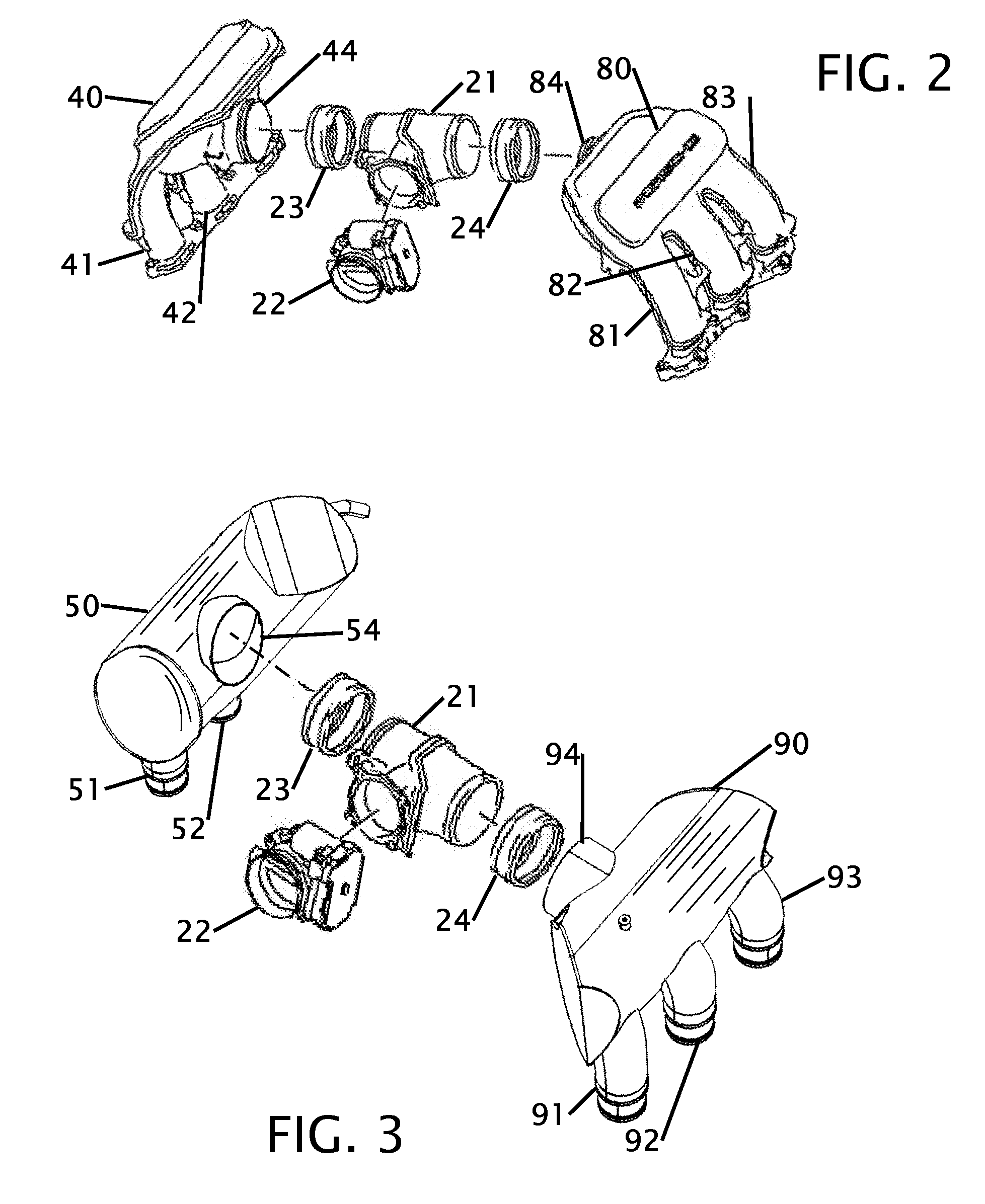
Figure 3
Abstract
Description
BACKGROUND OF THE INVENTION
[0001] 1. Field of the Invention
[0002] This invention relates to improvements in an air intake manifold. More particularly the intake manifold is directed to an automobile air intake manifold that is configured to improve air flow into an automobile engine.
[0003] 2. Description of Related Art including information disclosed under 37 CFR 1.97 and 1.98
[0004] An air intake manifold exists between the air filter and the head of an engine. This area is under a vacuum while the engine is in operation. The vacuum is caused by the pistons drawing in air. In general the faster the engine turns the greater amount of air passes through the intake manifold. The design and structure of the intake manifold has a significant effect on the performance of an engine. If the manifold has a restriction the volume of air is decreased. Obstructions and poor design of the manifold can cause turbulent air within the manifold and thereby decrease the efficiency of the engine. Several ...
Examples
Embodiment Construction
[0026]FIG. 1 shows a perspective view of a prior art motor with prior art plenums. This figure shows a typical configuration of an engine 20 with the plenum components. This figure is a stock Porsche engine 20. The air is brought into the engine from an air filter (not shown) where it is regulated through a throttle body (shown in FIG. 2). The throttle body is connected to a plenum T 21. The plenum T 21 diverts air from a single throttle body into two separate directions where the air flow then enters into a left plenum 40 and a right plenum 80. These prior art plenums have minimal internal volume and just split the air from a single input port to three intake conduits that are shown as items 41, 42 and 43 for the left stock plenum 40, and as items 81, 82 and 83 for the right stock plenum. The stock plenums are fabricated with a casting process. The stock air flow components are shown removed from the engine in FIG. 2 where they are more easily compared to the improved plenum design...