
Sealed crimp connection methods
Patent Information
- Authority / Receiving Office
- US · United States
- Current Assignee / Owner
- Publication Date
- 2011-04-14
Smart Images
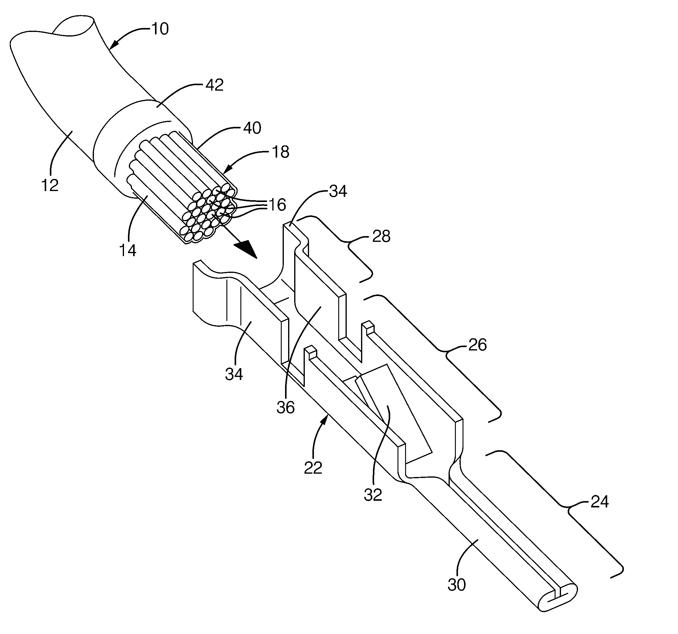
Figure 1 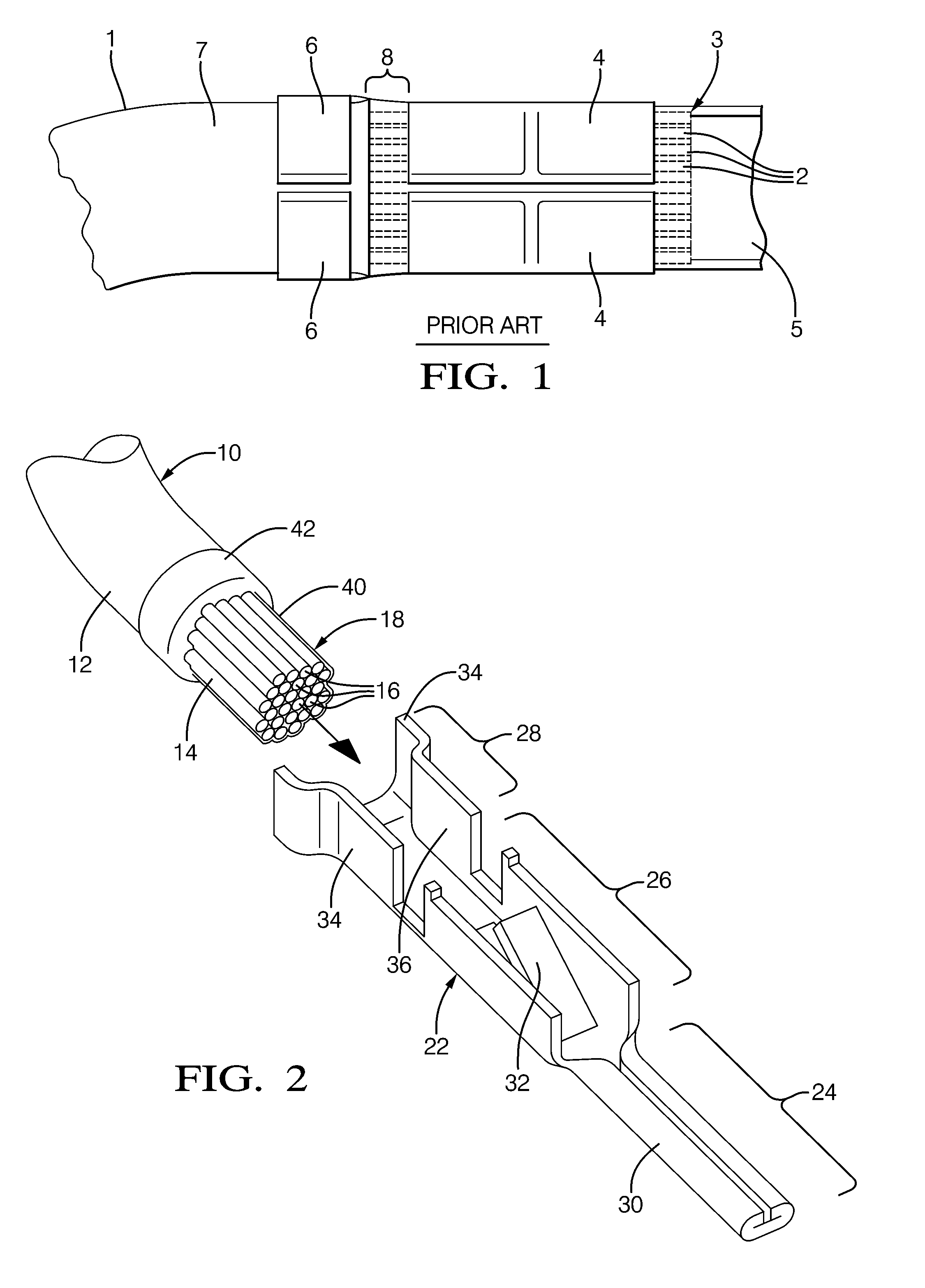
Figure 2 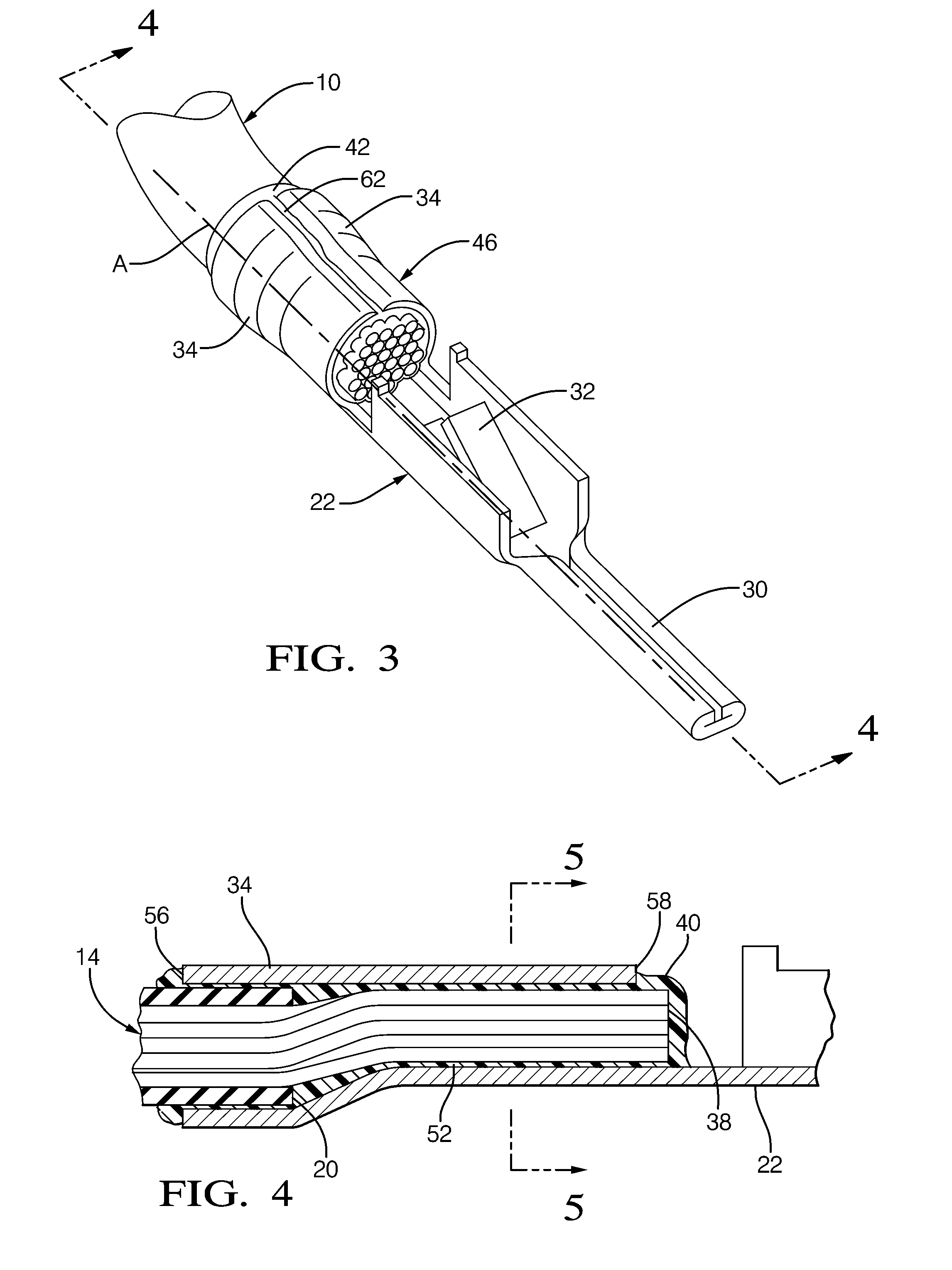
Figure 3
Abstract
Description
CROSS-REFERENCE TO CLAIM OF PRIORITY
[0001] This application is a continuation-in-part of U.S. application Ser. No. 12 / 582,158 filed 20 Oct. 2009, which is a continuation-in-part of U.S. application Ser. No. 12 / 575,689 filed on 8 Oct. 2009, which claims priority to U.S. Provisional Application U.S. Ser. No. 61 / 243,650.TECHNICAL FIELD
[0002] The invention relates to a connection between a terminal and a wire conductor.BACKGROUND OF INVENTION
[0003] Referring to FIG. 1, it is known to apply a sealant to a lead of the wire conductor (1) having wire strands (2) and crimp the sealed lead (3) to the core wings (4) of a terminal (5) and attach the terminal (5) to the wire conductor (1) that affords protection against contaminants that may negatively affect the electrical and mechanical operating performance therein. The insulator wings (6) of the terminal (5) are crimped to the insulative cover (7) of the wire conductor (1) and are spaced apart from the core wings (4) crimped to the sealed lead ...
Examples
Embodiment Construction
[0021]Referring to FIG. 2-6, a cable, or wire conductor 10 is disposed along a longitudinal axis A. Wire conductor 10 has an insulative outer cover 12 and an aluminum-based inner core 14. The term “aluminum based” as used in this document herein is defined to mean pure aluminum or an aluminum alloy where aluminum is the main metal in the alloy. Cover 12 surrounds inner core 14. Inner core 14 is constructed of a plurality of individual wire strands 16 that are bundled and twisted together. Wire strands 16 are useful to provide flexation of conductor 10 when conductor 10 is installed in a wiring application (not shown), such as during the manufacture of a vehicle. Alternately, the inner core of the wire conductor may be a single wire strand. An end portion (not shown) of cover 12 of conductor 10 is removed to expose a portion of inner core 14. Exposed portion of inner core 14 is a lead 18 of wire conductor 10. Lead 18 extends from an axial edge 20 of cover 12.
[0022]A copper-based term...