
Seat back frame
Patent Information
- Authority / Receiving Office
- US · United States
- Current Assignee / Owner
- Publication Date
- 2011-12-08
Smart Images
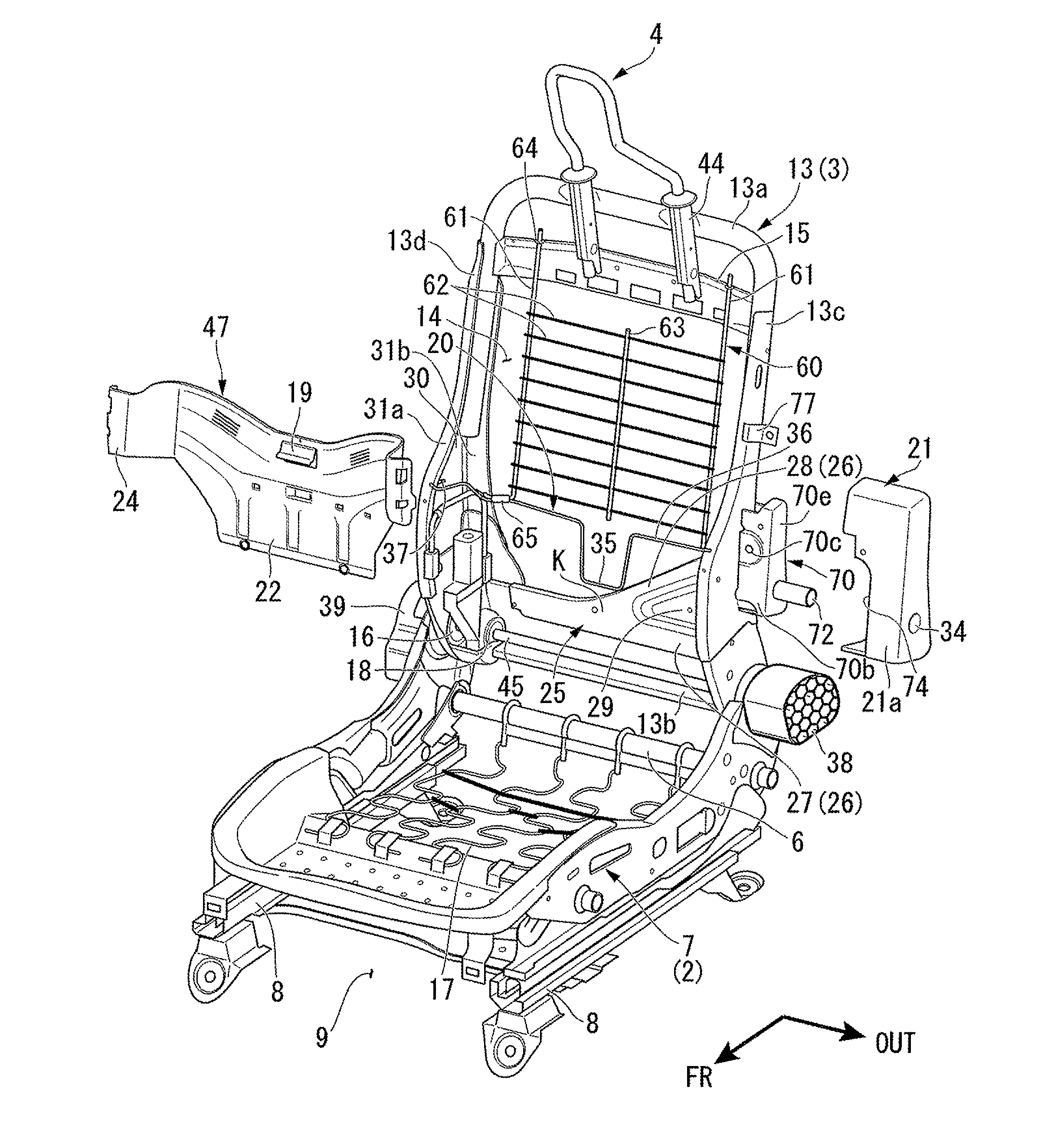
Figure 1 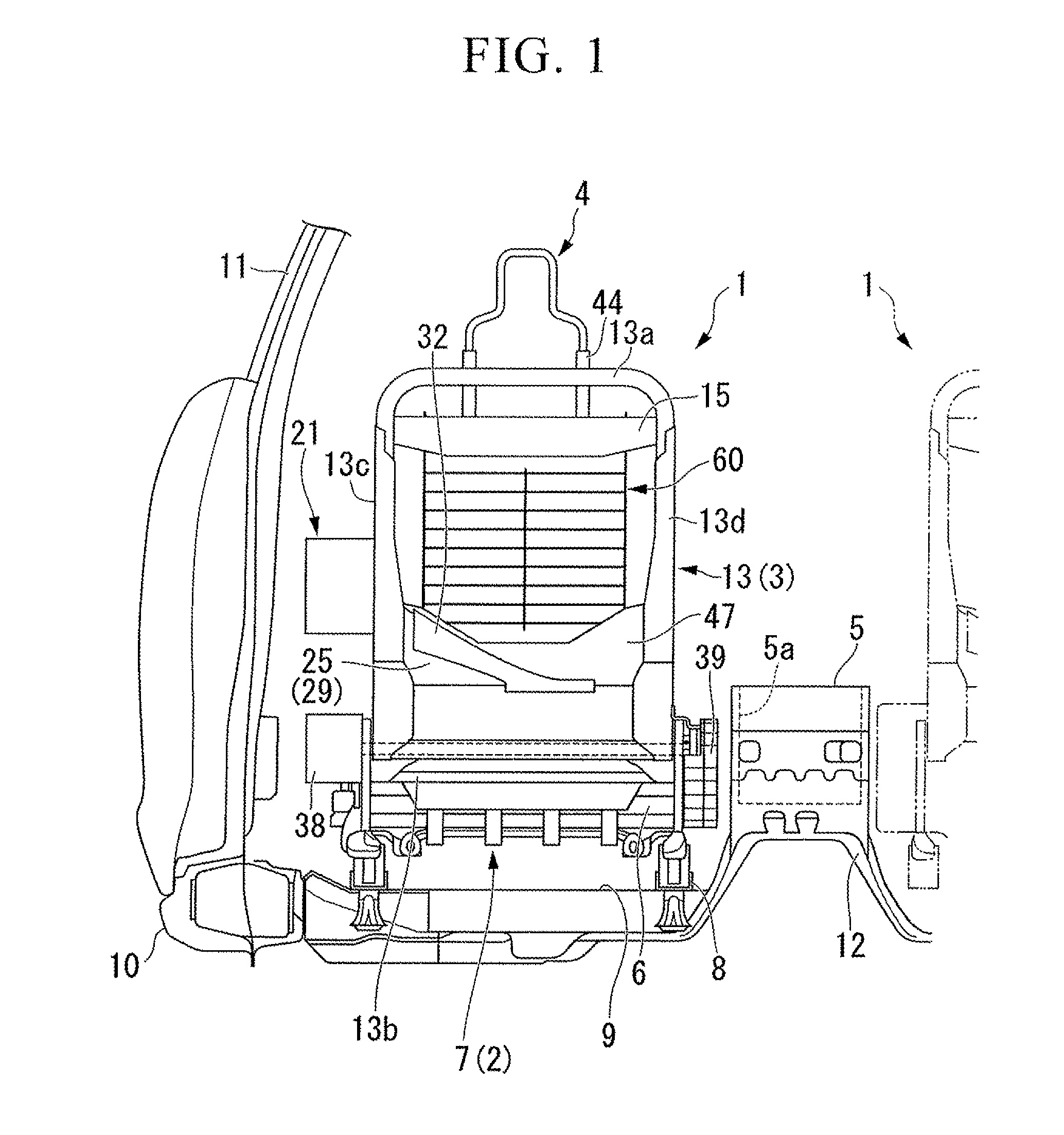
Figure 2 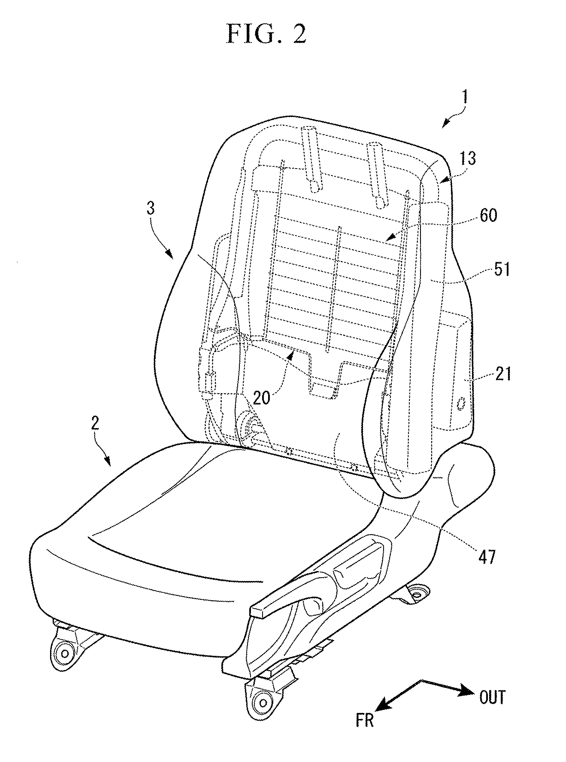
Figure 3
Abstract
Description
BACKGROUND OF THE INVENTION
[0001] The present application claims priority on Japanese Patent Application No. 2010-129224, filed Jun. 4, 2010, the content of which is incorporated herein by reference.
[0002] 1. Field of the Invention
[0003] The present invention relates to a seat back frame for a vehicle. The seat back frame comprises a feature such that a movement of an upper body of a passenger is controlled when an impact is entered from a rear part of the vehicle.
[0004] 2. Description of the Related Art
[0005] A seat back frame for a vehicle is suggested in Japanese Unexamined Patent
[0006] Application, First Publication No. H10-181400 (hereinafter referred to as Patent Document 1). This seat back frame is provided at a position corresponding to an upper portion of the pelvis of a passenger seated on a seat. In order to quickly reduce the space between the head part of the passenger and the head rest when an impact load is entered from a rear part of the vehicle, the seat back frame compri...
Examples
Embodiment Construction
[0031]Hereinafter, an embodiment of the present invention is described based on the attached diagrams.
[0032]FIG. 1 is a diagram showing a rear side of a front seat at a left side of a vehicle chamber. According to the diagram, the arrow FR indicates a frontal direction of the vehicle. The arrow OUT indicates an outer side of the vehicle in a vehicle width direction.
[0033]As shown in FIG. 1, a floor tunnel 12 is formed on a vehicle body floor 9 at a central portion of a vehicle width direction. The floor tunnel is shaped so as to be concaved upward along a front-rear direction of the vehicle body. At both sides of the floor tunnel 12, a pair of left and right from seats 1, 1, are positioned separately from one another.
[0034]At an outer side of the left and right seats 1, 1 in the vehicle chamber, a side sill 10 is provided in a front-rear direction of the vehicle body. The side sill 10 is configured to be a closed structure in cross sectional view. The side sill 10 is grafted to a ri...