
Thin film battery
a technology of thin film and primary batteries, applied in the direction of non-aqueous electrolyte cells, cell components, sustainable manufacturing/processing, etc., can solve the problems of not fully satisfying the above described batteries, the need for thin batteries having flexible housings, etc., and achieve the effect of convenient battery assembly and easy to obtain certain desired surface properties
Patent Information
- Authority / Receiving Office
- US · United States
- Patent Type
- Applications(United States)
- Current Assignee / Owner
- Publication Date
- 2013-05-30
- Estimated Expiration
- Not applicable · inactive patent
Smart Images
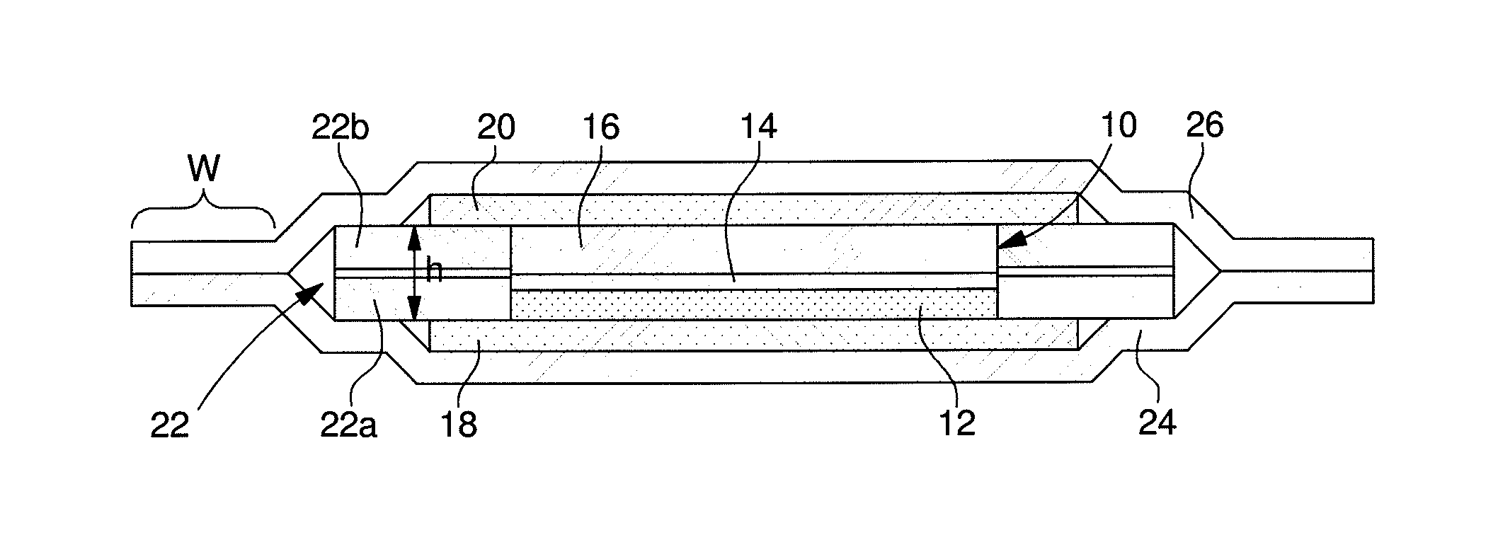
Figure 1 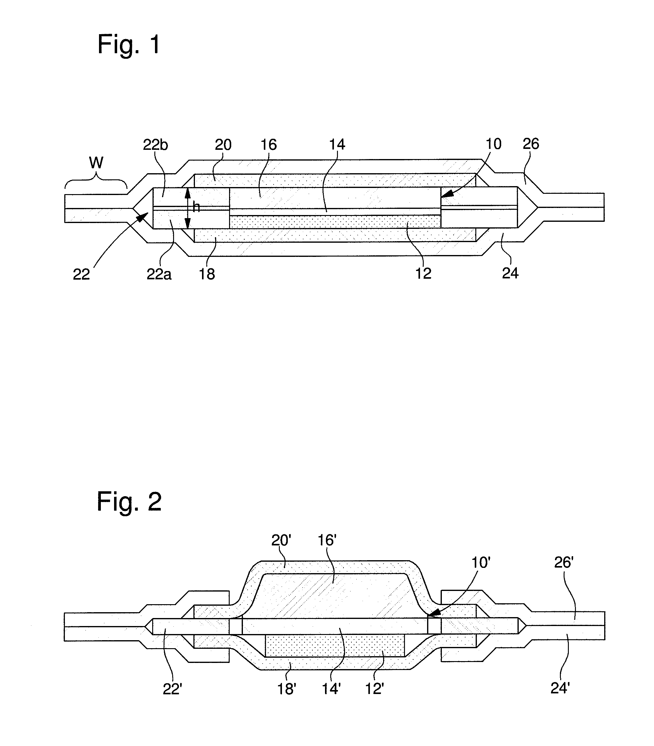
Figure 2 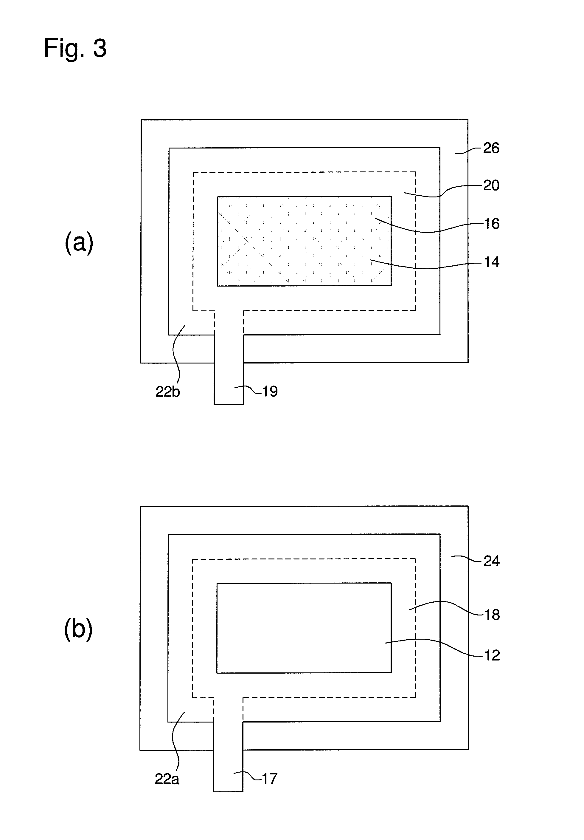
Figure 3
Abstract
Description
CROSS REFERENCE TO RELATED APPLICATION
[0001] This application is a divisional application of U.S. patent application Ser. No. 13 / 061,844, filed Apr. 18, 2011, which is a National Stage of International Application No. PCT / EP2008 / 061816 filed on Sep. 5, 2008, the contents of all of which are incorporated herein by reference in their entirety.BACKGROUND OF THE INVENTION
[0002] The present invention relates in general to thin film primary batteries.
[0003] Electrochemical elements, i.e. batteries, are known in many different physical forms. In most cases, they have a mechanically robust housing and are in the form of round, button or prismatic cells. A positive and a negative electrode, a separator and an electrolyte are arranged in such a cell. The housing of this type of cells is in general composed of steel, a stainless steel alloy or aluminum.
[0004] However, for certain applications very thin batteries having a flexible housing are needed. These applications include active radio frequenc...
Examples
Embodiment Construction
[0040]It will be appreciated that the following description is intended to refer to two specific embodiments of the invention which have been selected for illustration in the drawings but which are not intended to define or limit the invention, other than in the appended claims.
[0041]FIG. 1 shows a cross-section through a flat battery according to the invention, whereas FIGS. 3(a) and 3(b) each show a top view of a preassembled part of the flat battery shown in FIG. 1. More precisely, FIG. 3(a) shows the upper layers of the battery shown in FIG. 1, while FIG. 3(b) shows the lower layers of the same.
[0042]Referring to FIGS. 3(a) and 3(b), a method according to the invention to produce the battery as shown in FIG. 1 will now be described.
[0043]Firstly, the preassembly of the lower layers as shown in FIG. 3(b) will be described.
[0044]In a first step, a first rectangular polymeric sheet 24 being coated with a heat-sealable material on one side is provided. It should be noted that, altho...