
Wing shroud for an earth moving machine bucket, bucket and earth moving machine
a technology for earth moving machines and buckets, applied in the field of wing covers, can solve the problems of inability to replace protections, complicated and time-consuming, and inability to fix protections, etc., and achieve the effect of prolonging the life of buckets
Patent Information
- Authority / Receiving Office
- US · United States
- Current Assignee / Owner
- Publication Date
- 2014-03-27
Smart Images
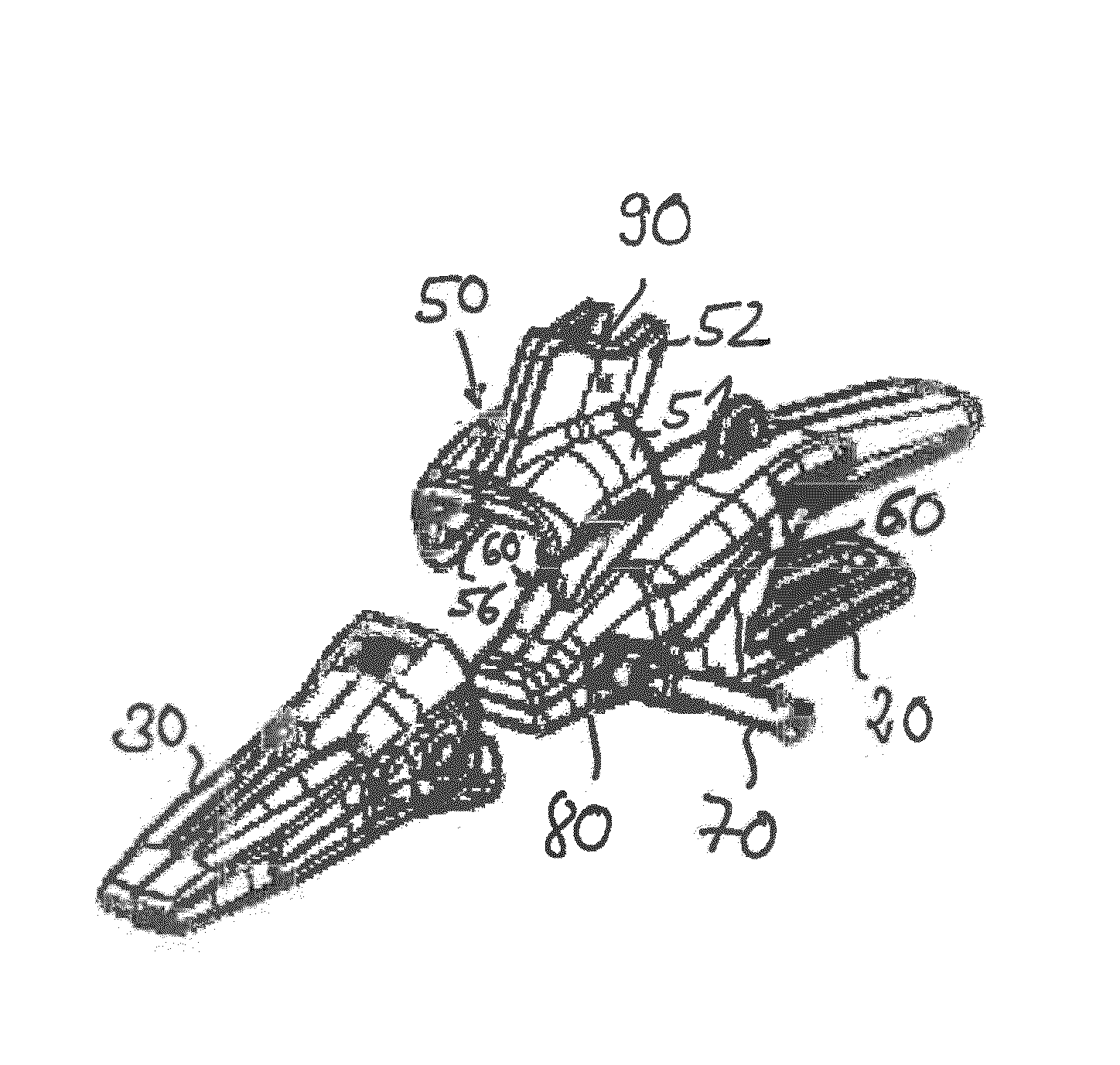
Figure 1 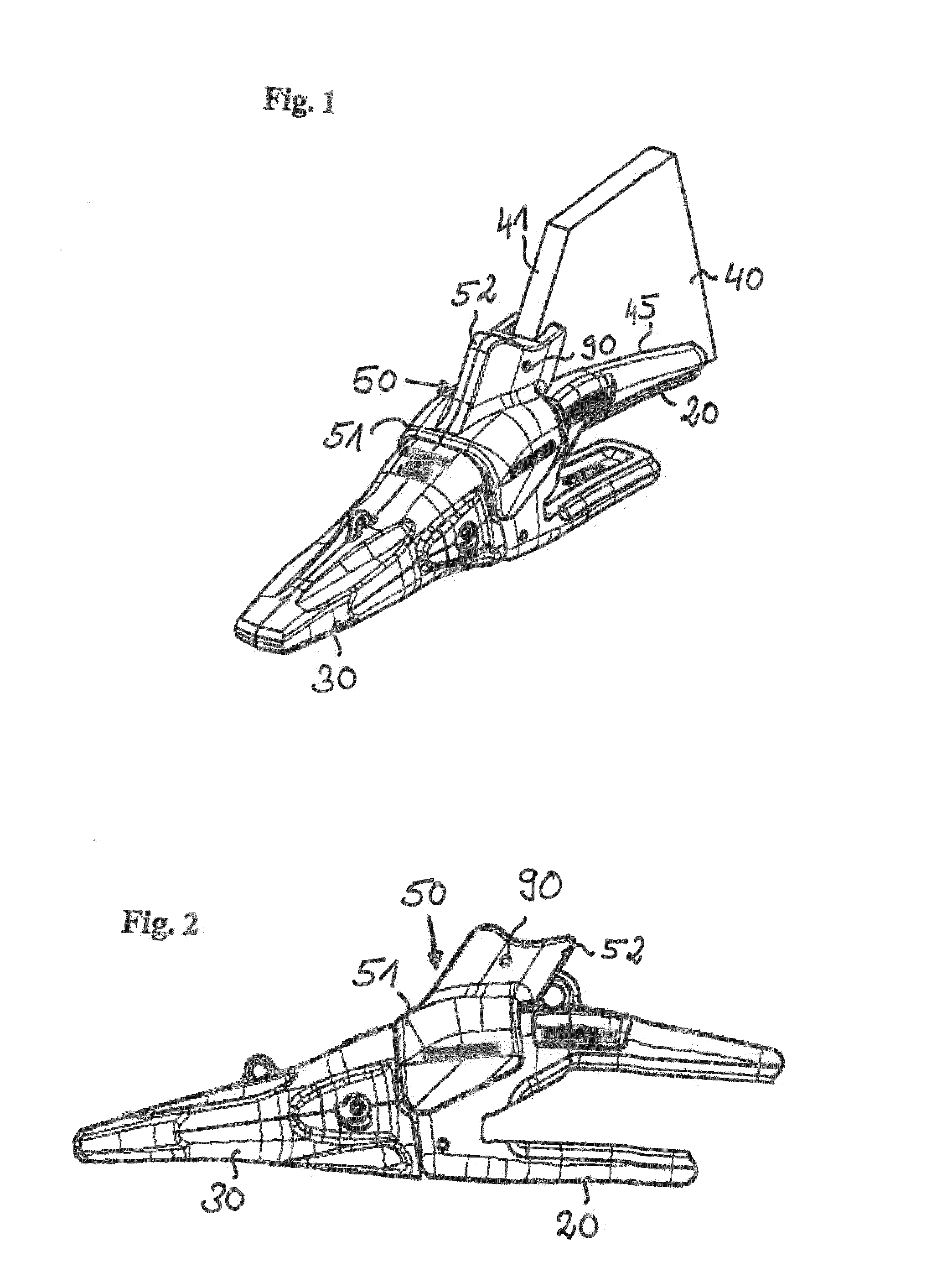
Figure 2 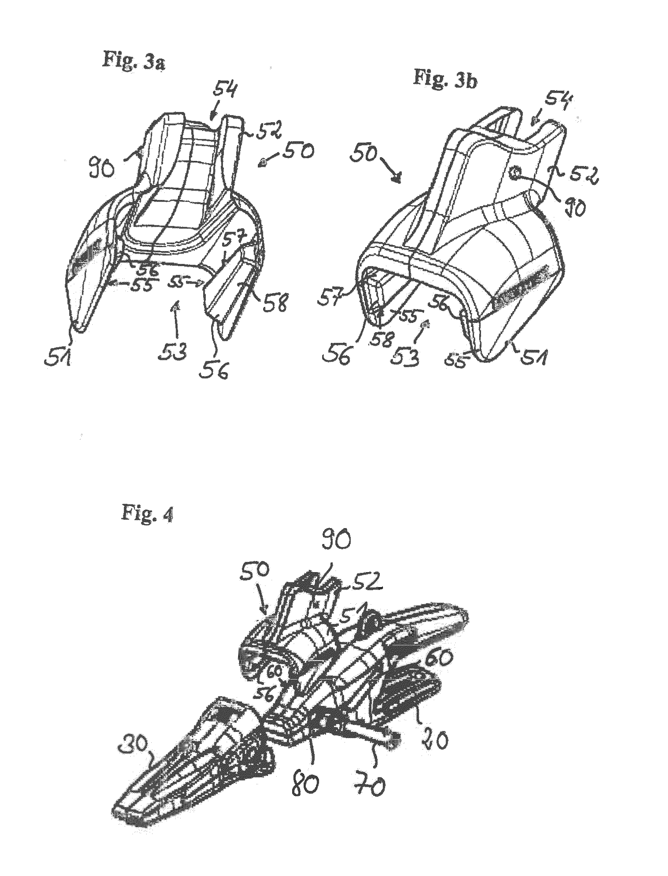
Figure 3
Abstract
Description
CROSS REFERENCE TO RELATED APPLICATION
[0001] This application claims priority to European Patent Application No. 12 006 636.0, entitled “Wing Shroud for an Earth Moving Machine Bucket, Bucket and Earth Moving Machine,” filed on Sep. 21, 2012, which is hereby incorporated by reference in its entirety for all purposes.TECHNICAL FIELD
[0002] The present disclosure is related to a wing shroud for protecting wear sensitive parts of an earth moving machine bucket.BACKGROUND AND SUMMARY
[0003] Shrouds are installed at different parts of a bucket for protecting defined bucket parts from abrasive wear. The installation of shrouds can prolong the bucket life since it will be sufficient to replace the outworn shrouds instead of purchasing a new bucket.
[0004] Currently, different kinds of shrouds are in use. For example, lip shrouds are placed on the leading edge of the bucket to protect the sensitive bucket edge parts which are strongly stressed during excavator work. Shrouds located at the bucket c...
Examples
Embodiment Construction
[0032]FIG. 1 shows a perspective front view of one bucket tooth assembly of the inventive bucket. The depicted assembly includes a corner tooth adapter 20 which is arranged at one of the outer edges of the bucket. The tooth adapter 20 is connected to a lateral plate of the bucket denoted as bucket side wall 40 by a connection line 45, in particular a welding line 45. However, other connection options than a welding line are possible. A suitable bucket tooth 30 can be attached to the tooth adapter 20 forming the tooth assembly.
[0033]A complete exposition of the inventive bucket 10 can be seen in FIG. 5. The bucket 10 comprises two corner tooth adapters 20 arranged at booth outer edges of the bucket 10 and three regular tooth adapters 21 arranged between booth corner tooth adapters 20.
[0034]To protect the top of the corner tooth adapter 20, the lateral bucket plate 40 as well as the welding line 45 between the corner adapter 20 and the bucket plate 40 a wing shroud 50 according to the...