
Test rig
a test rig and rotor technology, applied in the field of test rigs, can solve the problems of expensive maintenance and repair procedures, and excessive wear and material fatigue of various structural elements
Patent Information
- Authority / Receiving Office
- US · United States
- Current Assignee / Owner
- Publication Date
- 2014-05-01
- Estimated Expiration
- Not applicable · inactive patent
Smart Images
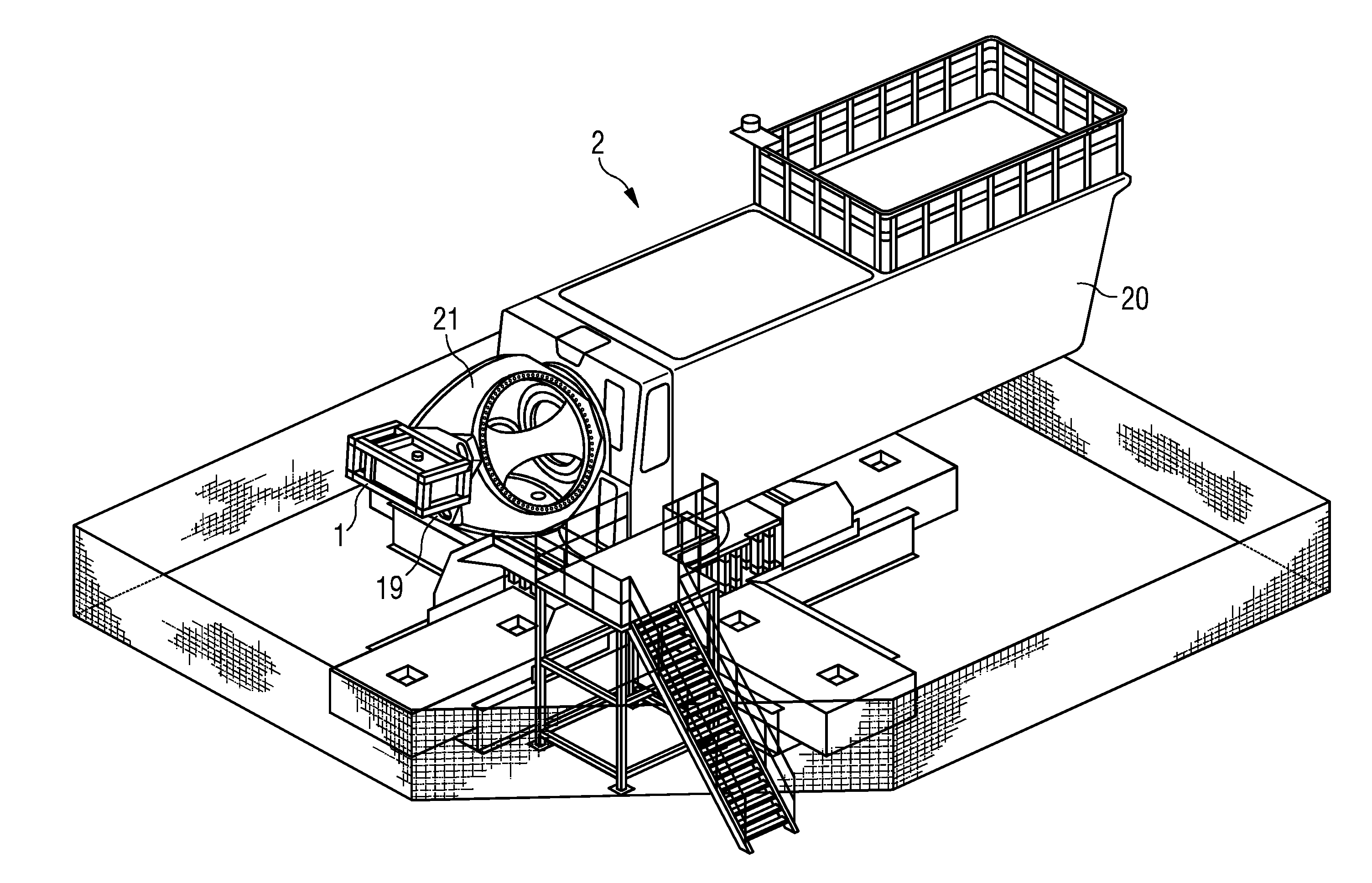
Figure 1 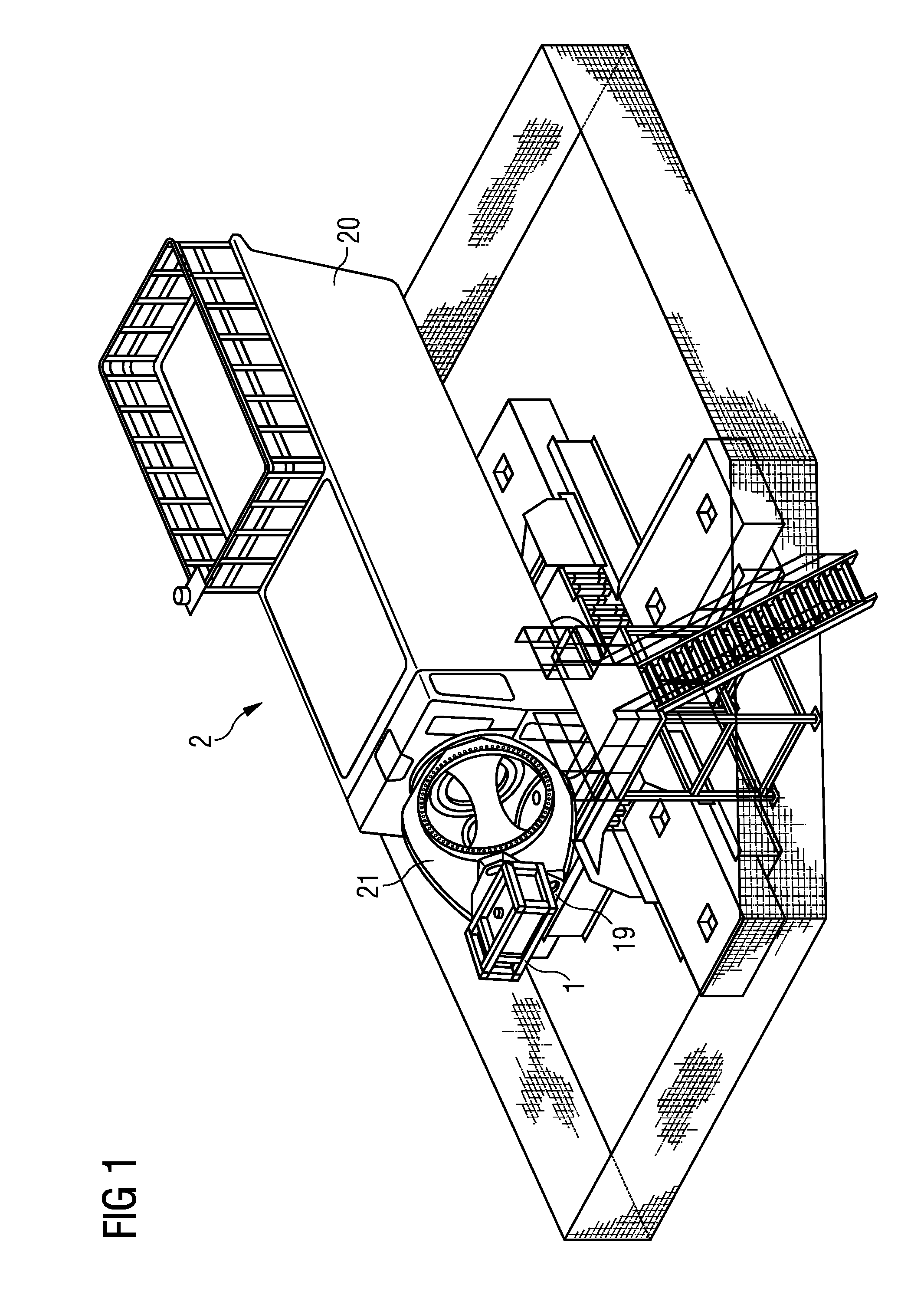
Figure 2 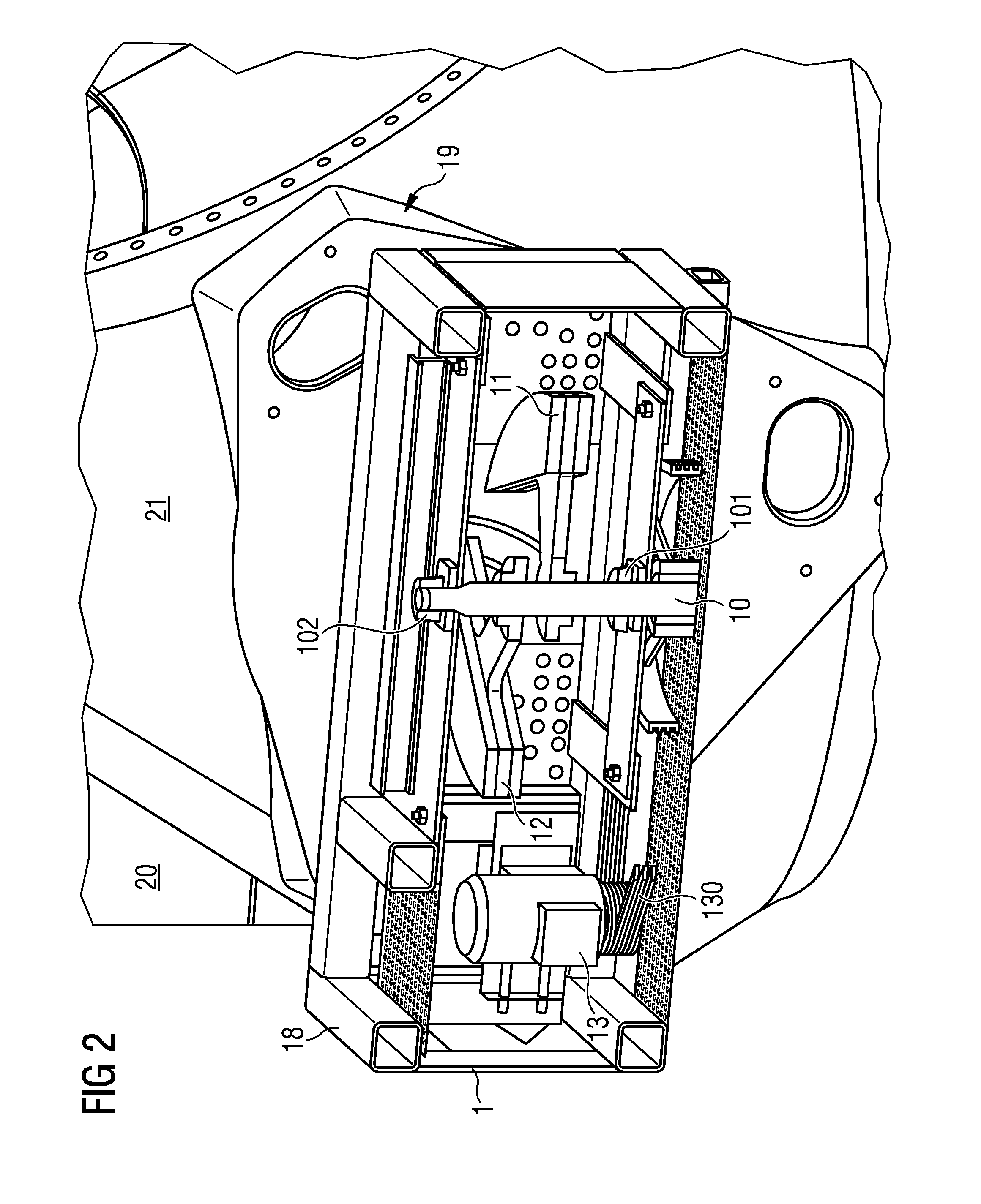
Figure 3
Abstract
Description
CROSS REFERENCE TO RELATED APPLICATIONS
[0001] The present application claims priority to European Patent Office application No. 12190856.0 EP filed Oct. 31, 2012, the entire content of which is hereby incorporated herein by reference.FIELD OF INVENTION
[0002] The invention describes a test rig for testing a component, a wind turbine test rig, and a method of testing a component.BACKGROUND OF INVENTION
[0003] Certain structures such as tall towers, wind turbines, etc. are subject to structural loading during their lifetime. For example, the forces acting on a wind turbine nacelle and tower during operation of the wind turbine can result in excessive wear and material fatigue of various structural elements such as bearings, nacelle, bedframe hub, yaw ring, etc. Excessive wear on parts such as bearings can require expensive maintenance and repair procedures, while material fatigue can lead to the development of hairline cracks or larger cracks, ultimately leading to serious damage and compo...
Examples
Embodiment Construction
[0043]In the diagrams, like numbers refer to like objects throughout. Objects in the diagrams are not necessarily drawn to scale.
[0044]FIG. 1 shows an embodiment of a wind turbine test setup 2 according to the invention. The component under test comprises a nacelle 20 and hub 21 of a wind turbine. The same type of model can be used as would be used in real-life, and the nacelle 20 can be mounted on a tower model (for example a short-spring arrangement) that imitates the behaviour of an appropriate tower construction. To imitate the effects of the rotor blade rotation and wind loading, a test rig 1 according to the invention is mounted securely to the hub 21 by means of an adapter 19 or connecting means 19 so that centrifugal forces generated in the test rig are transferred essentially undiminished as lateral forces F to the hub 21 and nacelle 20.
[0045]FIG. 2 shows a partial cut-away of an embodiment of a test rig 1 according to the invention. The test rig 1 comprises a cage 18 or fr...