
Motor Water-Cooling Structure and Manufacturing Method Thereof
a technology of water cooling structure and motor, which is applied in the direction of cooling/ventilation arrangement, dynamo-electric components, light and heating apparatus, etc., can solve the problems of reducing the working affecting the efficiency of the motor, and the air cooling appears to have only limited effect in removing the produced heat from the motor, so as to reduce material, labor and time costs, and avoid the risk of water leakage , the effect of saving manufacturing costs
Patent Information
- Authority / Receiving Office
- US · United States
- Patent Type
- Applications(United States)
- Current Assignee / Owner
- Publication Date
- 2014-09-25
- Estimated Expiration
- Not applicable · inactive patent
Smart Images
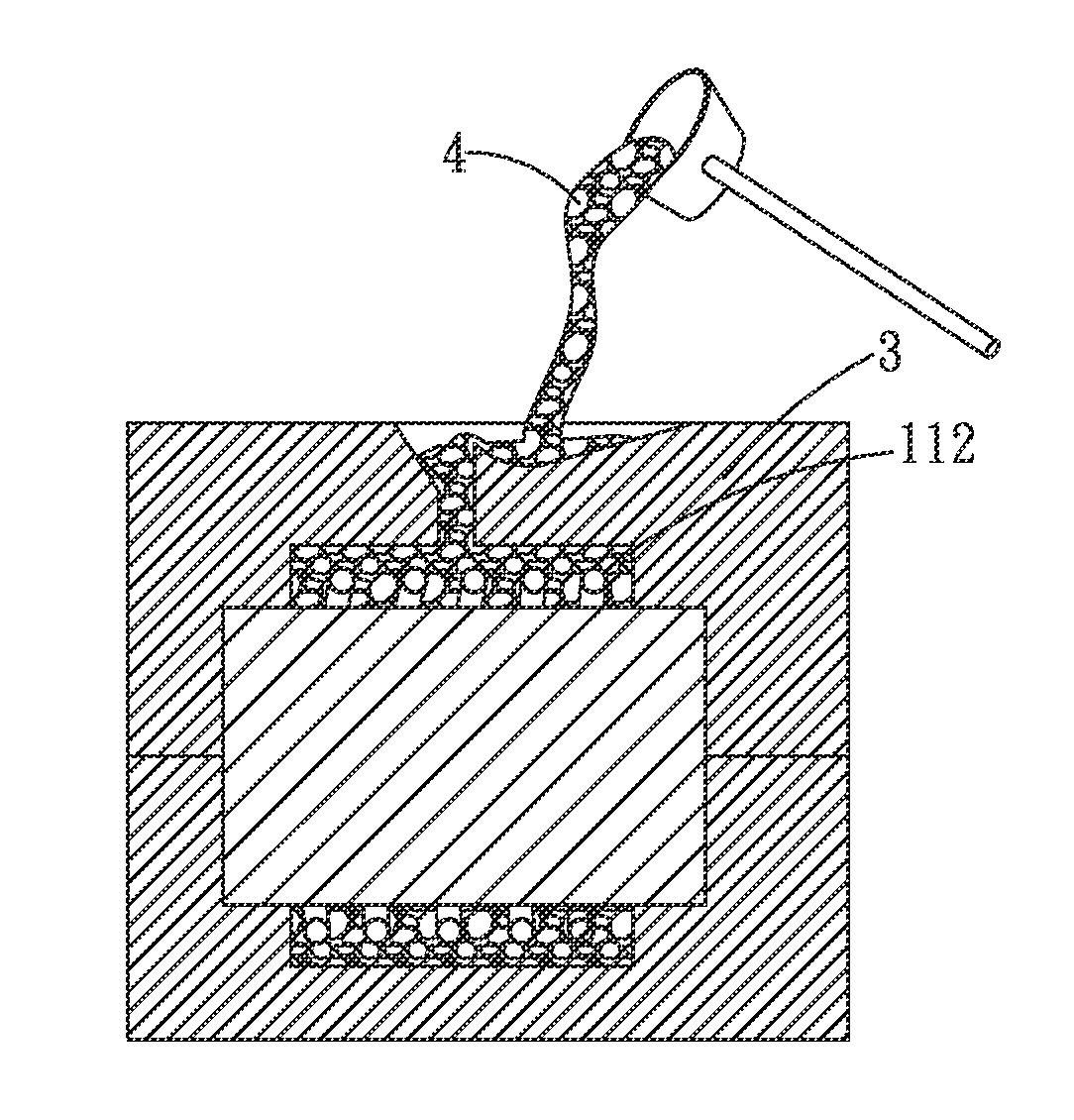
Figure 1 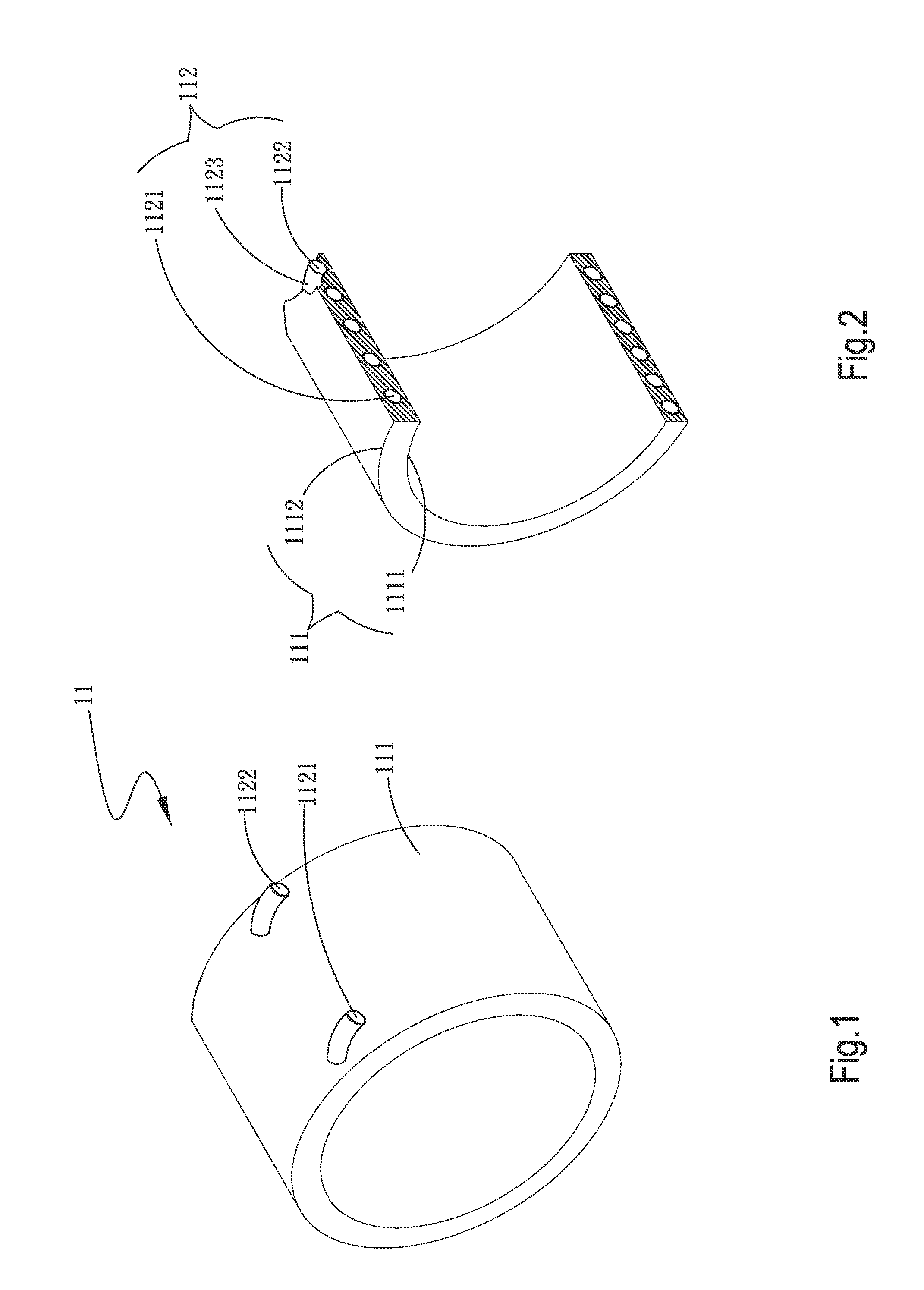
Figure 2 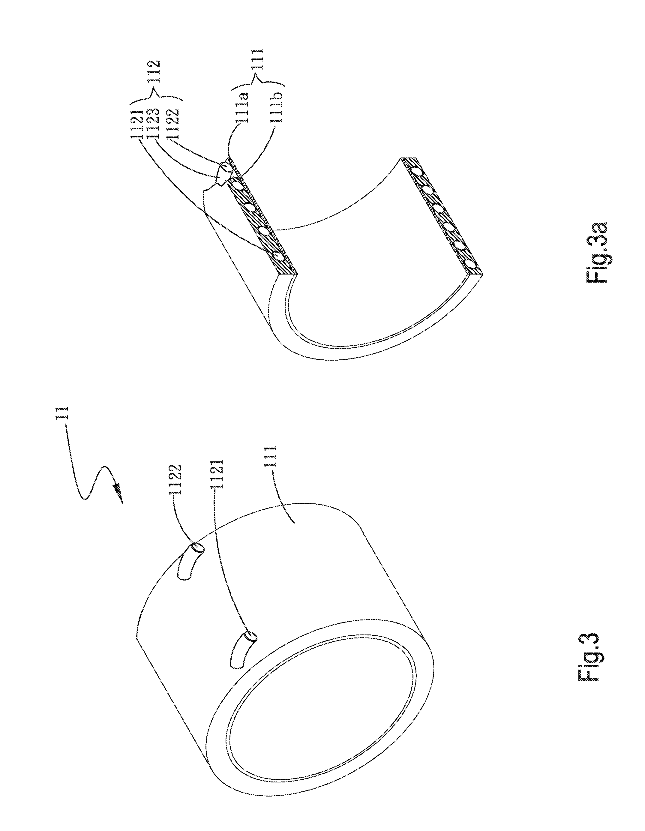
Figure 3
Abstract
Description
[0001] This application claims the priority benefit of Taiwan patent application number 100102805 filed on Jan. 26, 2011.FIELD OF THE INVENTION
[0002] The present invention relates to a motor water-cooling structure and a manufacturing method thereof; and more particularly to a motor water-cooling structure that includes a motor case formed of one or more types of materials, and a tube embedded in the motor case to serve as a water passage, so as to reduce the manufacturing cost and avoid the risk of water leakage.BACKGROUND OF THE INVENTION
[0003] A motor is a prerequisite machine for energy conversion. There are motors that convert electric energy into kinetic energy, such as the motors for fans, water pumps and the like. There are also motors that convert kinetic energy into electric energy, such as power generators. Most of the currently available motors are used for the above-mentioned applications. Either the motors for converting electric energy into kinetic energy or the motors f...
Examples
first embodiment
[0043]In a first step S1 according to the manufacturing method, a mold having a mold cavity and a tube are provided.
[0044]More specifically, as can be seen from FIGS. 6 and 7, a mold 2 having a mold cavity 21 is provided. The mold cavity 21 is dimensioned corresponding to a motor case that is to be formed, such as the motor case 11 shown in FIGS. 1 and 2. And, a tube, such as the tube 112 shown in FIGS. 1 and 2, is also provided.
[0045]Then, in a second step S2, the tube is positioned in the mold cavity of the mold, and a motor case is formed by pour molding to embed the tube therein.
[0046]More specifically, as can be seen from FIGS. 6 and 7, the tube 112 is positioned in the mold cavity 21 of the mold 2, and a motor case, e.g. the motor case 11, is formed by injection molding a plastic material or a metal material in the mold 2, so that the tube 112 is embedded in the motor case (e.g. the motor case 11) to serve as a flow passage in the molded motor case 11.
[0047]FIG. 5 also shows t...
third embodiment
[0052]In a first step X1 according to the manufacturing method, a mold having a mold cavity, a first motor case, and a tube are provided.
[0053]More specifically, as can be seen from FIGS. 11 and 12, a mold 2 having a mold cavity 21 is provided. And, a first motor case, such as the first part 111a shown in FIGS. 3 and 3a, and a tube, such as the tube 112 shown in FIGS. 3 and 3a, are also provided.
[0054]Then, in a second step X2, the tube is wound around an outer side of the first motor case, and the first motor case with the tube wound therearound is positioned in the mold cavity of the mold; and a second motor case is formed on an outer side of the first motor case to cover the first motor case and the tube, so that the second motor case, the first motor case and the tube form an integral body.
[0055]More specifically, as can be seen from FIGS. 11 and 12, the tube 112 is wound around the outer side of the first motor case (e.g. the first part 111a), and the first motor case with the ...
fifth embodiment
[0061]In a first step Y1 according to the manufacturing method, a mold having a mold cavity, a first motor case having a groove provided on an outer side thereof, and a tube are provided.
[0062]More specifically, as can be seen from FIGS. 16 and 17, a mold 2 having a mold cavity 21 is provided. And, a first motor case, such as the first part 111a shown in FIGS. 4 and 4a, having a groove (e.g. the groove 111c) provided on an outer side thereof, and a tube, such as the tube 112 shown in FIGS. 4 and 4a, are also provided.
[0063]Then, in a second step Y2, the tube is set in the groove on the outer side of the first motor case, and the first motor case with the tube set in the groove is positioned in the mold cavity of the mold; and a second motor case is formed on an outer side of the first motor case to cover the first motor case and the tube, so that the second motor case, the first motor case and the tube form an integral body.
[0064]More specifically, as can be seen from FIGS. 16 and 1...