
Head mounted display apparatus
a display device and head mounted technology, applied in static indicating devices, instruments, optical elements, etc., can solve the problem that the image of the hand which has been detected cannot be picked up by the user moving the hand, and achieve the effect of improving the detection accuracy of the hand, improving convenience, and reliably recognized by the user
Patent Information
- Authority / Receiving Office
- US · United States
- Current Assignee / Owner
- Publication Date
- 2015-03-05
Smart Images
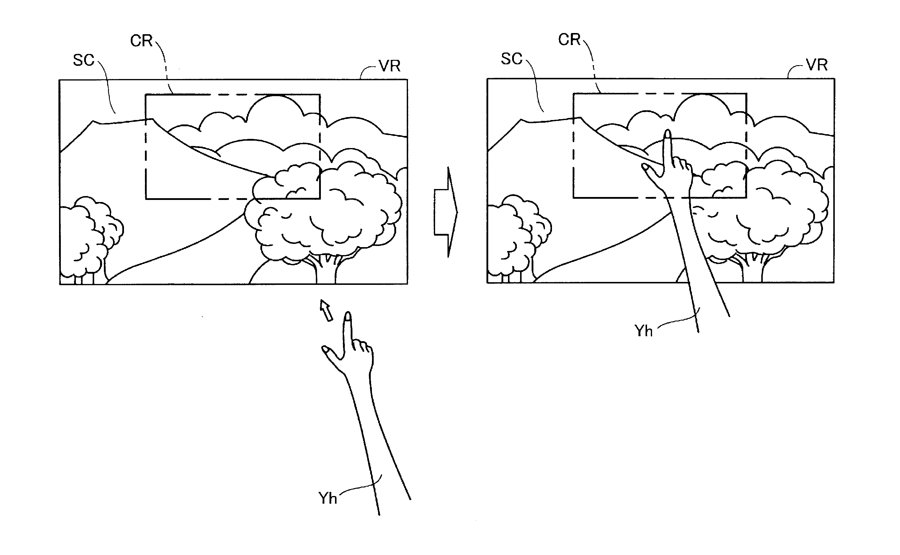
Figure 1 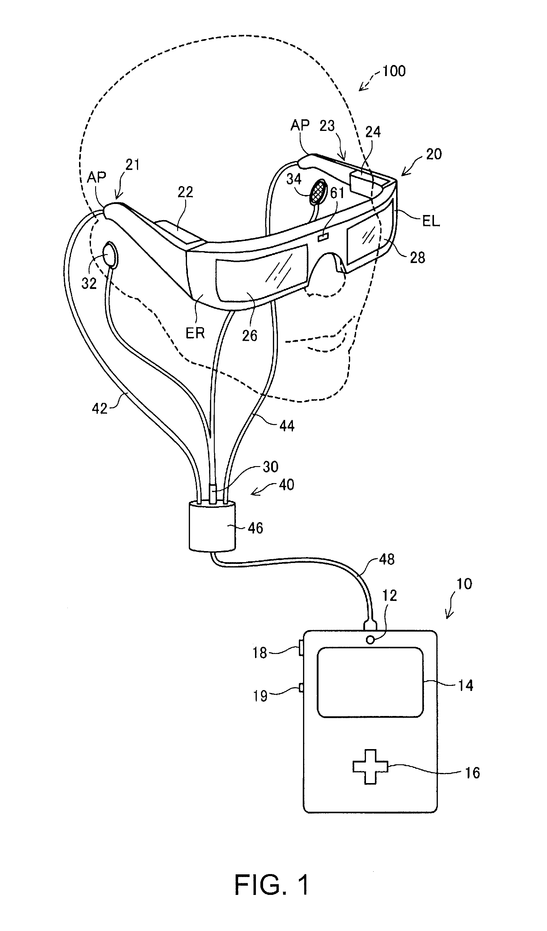
Figure 2 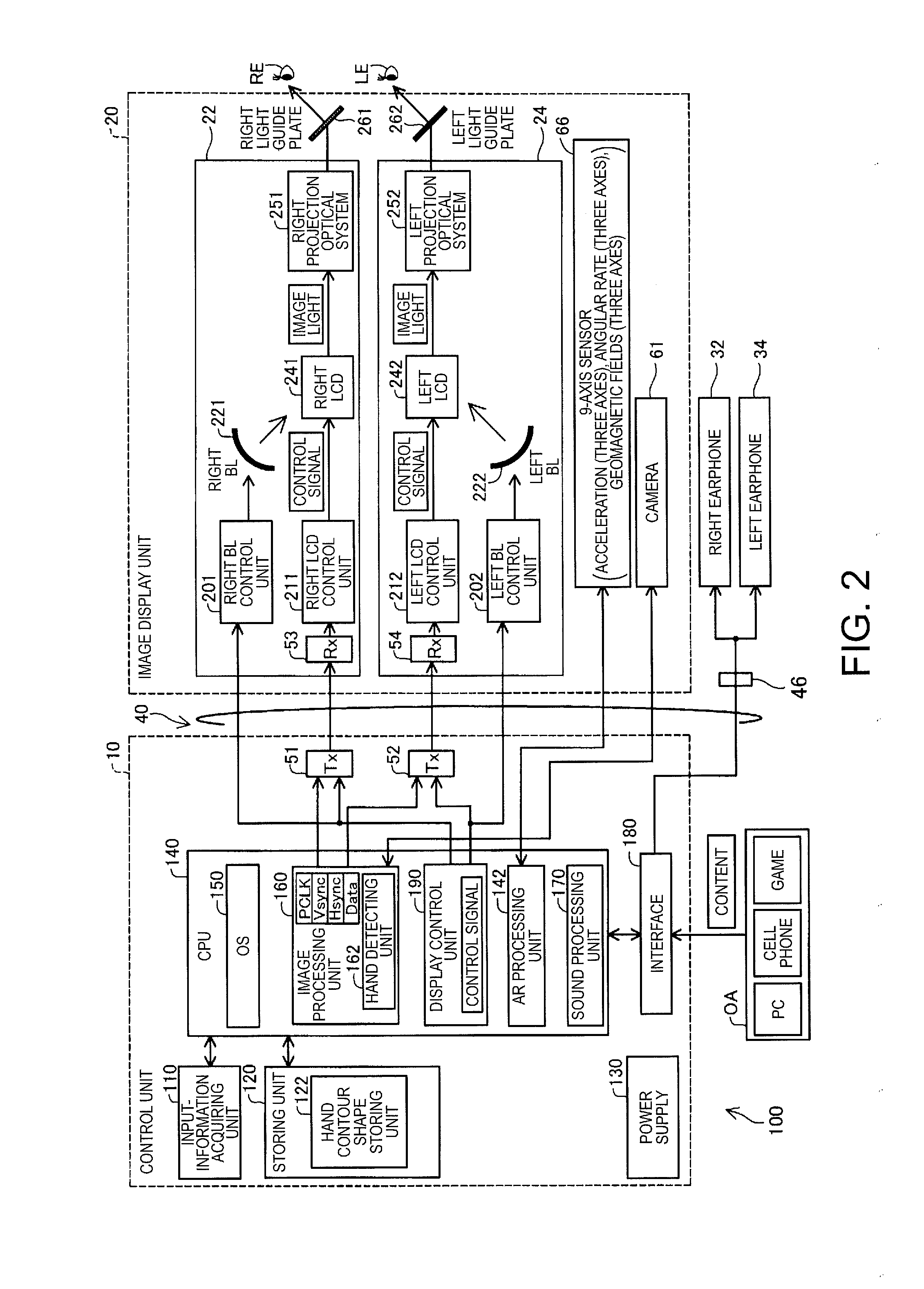
Figure 3
Abstract
Description
BACKGROUND
[0001] 1. Technical Field
[0002] The present invention relates to a head mounted display apparatus.
[0003] 2. Related Art
[0004] A technique called Augmented Reality (AR) for adding information to a real environment and presenting the information using a computer is known. A technique for realizing such augmented reality is applied to not only head mounted display (HMD) apparatuses (for example, refer to JP-A-2010-146481) but image processing devices (for example, refer to “Handy AR: Markerless Inspection of Augmented Reality Objects Using Fingertip Tracking”) which display an image on the existing displays other than HMDs. The HMD disclosed in JP-A-2010-146481 allows the user to visually recognize a virtual panel formed by augmented reality as a virtual image, picks up images of a position and a movement of a hand of the user with a camera, and associates image pickup positions thereof with the virtual panel. Therefore, a technique for recognizing the hand of the user is necessa...
Examples
embodiment-1
A-4. Other Embodiment-1
[0090]The head mounted display 100 can be embodied as follows. FIG. 15 is a diagram schematically illustrating hand recognition processing which is executed by a head mounted display 100 according to another embodiment of the invention. In this embodiment, the scanning input of the image pickup data in Step S100 and the difference calculation in Step S102 subsequent thereto are executed in the execution order determined for each divided region into which the image pickup region CR is divided in advance. That is, as illustrated in FIG. 15, the image pickup region CR is divided into a left end region CRL, a right end region CRR, a lower end region CRD, and a residual region CRU in advance, and the scanning input of data in the horizontal direction for each divided region is executed in the following order: the right end region CRR→the lower end region CRD→the left end region CRL. Typically, the user puts the dominant hand Yh into the image pickup region CR of th...
embodiment-2
A-5. Other Embodiment-2
[0091]In a head mounted display 100 according to another embodiment of the invention, RGB-based image pickup data to be input in Step S100 is color-converted into HSV color-based data in which the color is represented by hue, saturation, and value. The color difference calculation between adjacent pixels in the next step S102 is replaced with calculation of a difference between values of adjacent pixels obtained by the color conversion. The value obtained by the color conversion of the image pickup data is separated from the brightness affected by the illuminance around the imaged hand Yh of the user during the color conversion into the HSV color system. Therefore, according to the head mounted display 100 of the embodiment using the value obtained by the color conversion into the HSV color system, a decrease in the recognition accuracy by the rapid change in illuminance can be suppressed with higher effectiveness, and the recognition accuracy of the hand Yh c...
embodiment-3
A-6. Other Embodiment-3
[0092]FIG. 16 is a diagram illustrating a schematic configuration of a head mounted display 100 according to another embodiment of the invention. In this embodiment, the above-described camera 61 is used only for picking up images of the outside scene SC, and a camera 61a used only for recognizing the hand Yh of the user is further provided at the end ER of the image display unit 20. FIG. 17 is a diagram schematically illustrating a relationship between an image pickup region CR of the camera 61a, which is positioned at the end ER of the image display unit 20, and a visual field VR of the user. As illustrated inFIG. 17, the image pickup region CR of the camera 61a deviates from a region on the right end side of the visual field VR of the user or from the visual field VR due to the camera installation position. Therefore, when the hand Yh in the image pickup region CR does not substantially enter the outside scene SC in the visual field VR, and the outside scen...