
Radar system with phase based multi-target detection
Patent Information
- Authority / Receiving Office
- US · United States
- Current Assignee / Owner
- Publication Date
- 2016-03-24
Smart Images
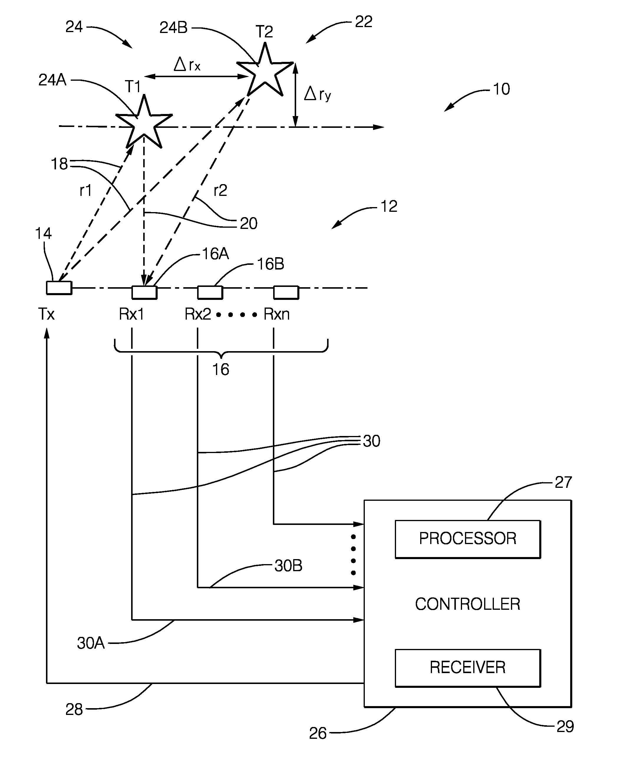
Figure 1 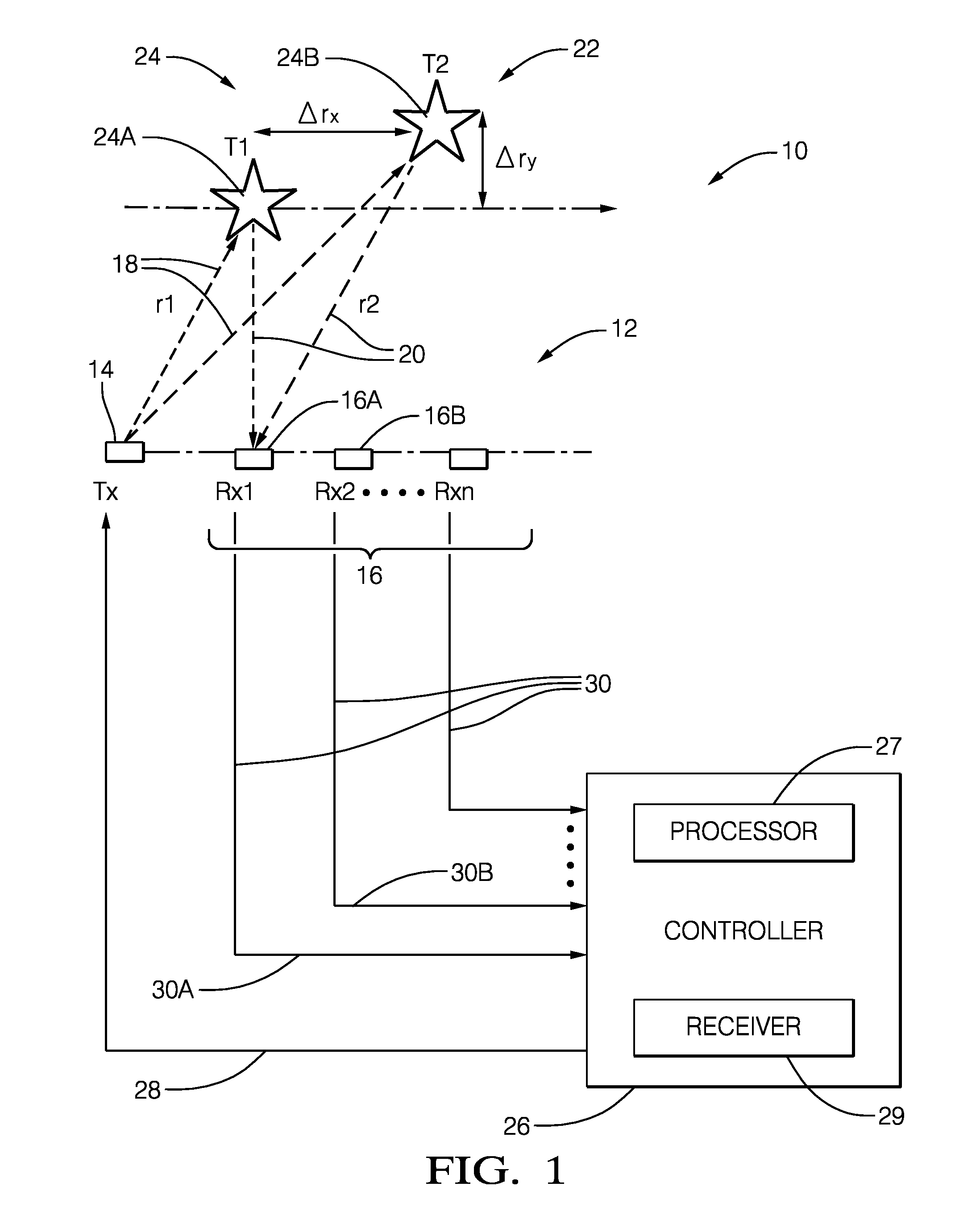
Figure 2 
Figure 3
Abstract
Description
TECHNICAL FIELD OF INVENTION
[0001] This disclosure generally relates to a radar system, and more particularly relates to a system that determines if a target includes more than one object based on a comparison of phases of detected signals from multiple receive antennas.BACKGROUND OF INVENTION
[0002] Because of antenna size, system size, technology, and cost constraints, automotive radar sensors may have performance limitations with regard to discriminating two objects that have similar position and Doppler shift characteristics, or if one object has a substantially larger Radar Cross Section (RCS) than a second nearby object. Examples of two objects with similar range and Doppler shift reflection characteristics that typical automotive radar systems have difficulty discerning include: a slowly moving pedestrian walking around stationary or slowly moving passenger vehicle, a motor cycle traveling beside a tractor-trailer traveling in an adjacent lane at a similar range and range rate, ...
Examples
Embodiment Construction
[0023]FIG. 1 illustrates a non-limiting example of a radar system, hereafter referred to as the system 10. The system 10 includes an antenna array 12 that may include a transmit-element 14, and an array of receive elements, hereafter referred to as a plurality of antennas 16. It is recognized that one or more of the antenna elements that make up the antenna array 12 could be used to both transmit a radar signal 18, and output a detected signal 30 indicative of reflected radar signals 20 reflected by a first object 24A or a second object 24B in a field-of-view 22 of the system 10. The transmit-element 14 and the plurality of antennas 16 are illustrated as distinct elements in this example only to simplify the explanation of the system 10.
[0024]The system 10 may also include a controller 26 configured to output a transmit-signal 28 to the transmit-element 14, and configured to receive detected signals 30 from each antenna, for example a first signal 30A from a first antenna 16A and a ...