
Shunt resistance type current sensor
a current sensor and resistance type technology, applied in the direction of instruments, base element modifications, measurement devices, etc., can solve the problems of failure to meet the requirements of the application, and etc., to achieve the effect of easy deformation, reduced heat dissipation of each connection terminal, and reduced difficulty in soldering work to the circuit board
Patent Information
- Authority / Receiving Office
- US · United States
- Patent Type
- Applications(United States)
- Current Assignee / Owner
- Publication Date
- 2016-04-21
- Estimated Expiration
- Not applicable · inactive patent
Smart Images
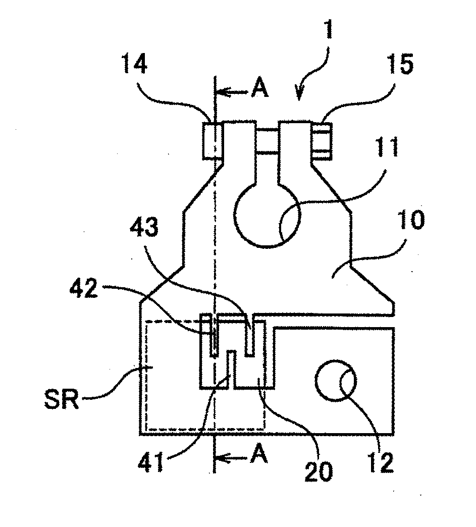
Figure 1 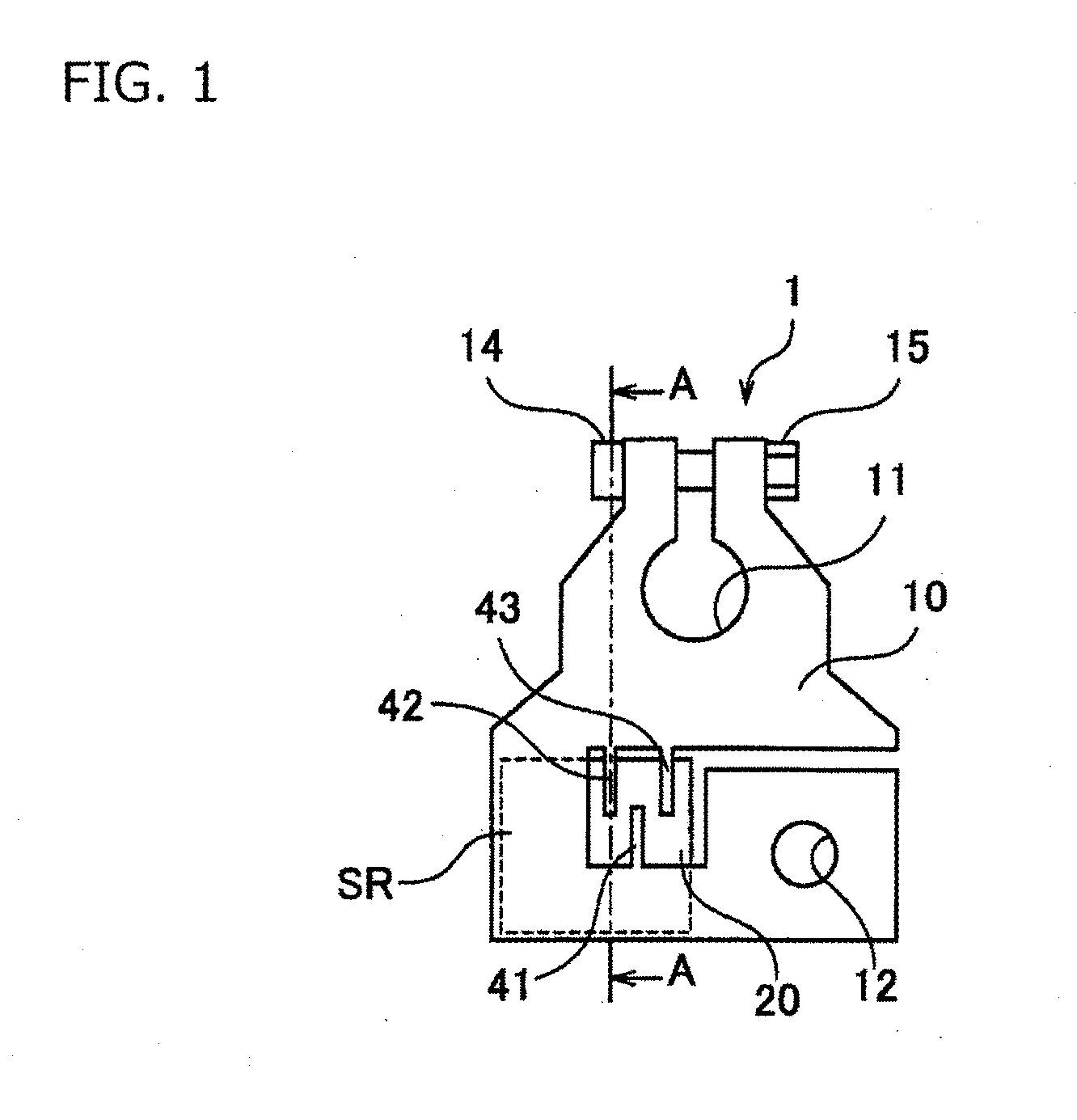
Figure 2 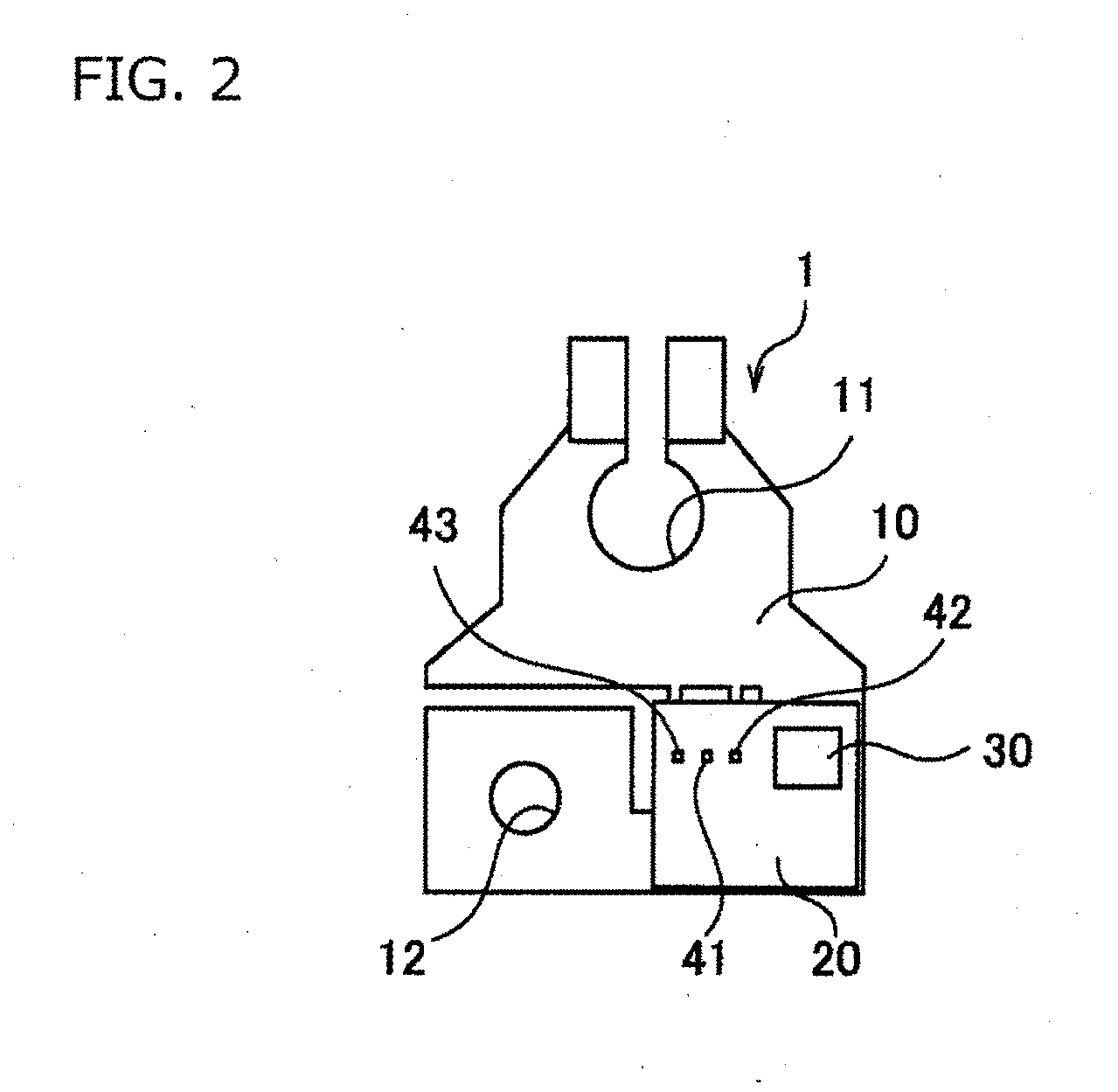
Figure 3
Abstract
Description
CROSS REFERENCE TO RELATED APPLICATIONS
[0001] This application is a continuation of PCT application No. PCT / JP2014 / 067089, which was filed on Jun. 26, 2014 based on Japanese Patent Application (No. 2013-149283) filed on Jul. 18, 2013, the contents of which are incorporated herein by reference.BACKGROUND OF THE INVENTION
[0002] 1. Field of the Invention
[0003] One or more embodiments of the present invention relate to a shunt resistance type current sensor.
[0004] 2. Description of the Related Art
[0005] There has been proposed a shunt resistance type current sensor in which current to be measured flows into a shunt resistor having a known resistance value in order to detect a pulse current, a large AC current or the like, and a voltage drop generated across the shunt resistor is detected, thereby measuring a magnitude of the current to be measured. For example, in a vehicle such as an automobile, a metal piece called a bus bar is sometimes used for power distribution, and a part of the bus b...
Examples
Embodiment Construction
[0036]FIG. 1 is a top view schematically showing a shunt resistance type current sensor 1 according to an embodiment. FIG. 2 is a bottom view schematically showing the shunt resistance type current sensor 1 according to the embodiment. FIG. 3 is a side view schematically showing the shunt resistance type current sensor 1 shown in FIG. 1 and shows a state of the shunt resistance type current sensor 1 shown in FIG. 1 seen from a lower side of the sheet. The shunt resistance type current sensor 1 is used as a battery terminal and mainly configured of a bus bar 10 and a circuit board 20.
[0037]The bus bar 10 is a conductive member of a substantially flat plate shape and constituted of, for example, copper-manganese alloy, copper-nickel-alloy or the like. A part of the bus bar 10 can be acted as a shunt resistance part SR. The bus bar is configured in a manner that current to be measured flows in the shunt resistance part SR when current flows in the bus bar 10. The bus bar 10 is formed t...