
Bicycle Rear Derailleur with a Damper Assembly
a technology of derailleur and damper assembly, which is applied in the direction of mechanical equipment, transportation and packaging, and machining, etc., can solve the problems of increasing the risk of a subsequent reduction of the chain tensioning below the necessary level, and reducing the chain tensioning with unwanted slackness
Patent Information
- Authority / Receiving Office
- US · United States
- Patent Type
- Applications(United States)
- Current Assignee / Owner
- Publication Date
- 2016-06-23
Smart Images
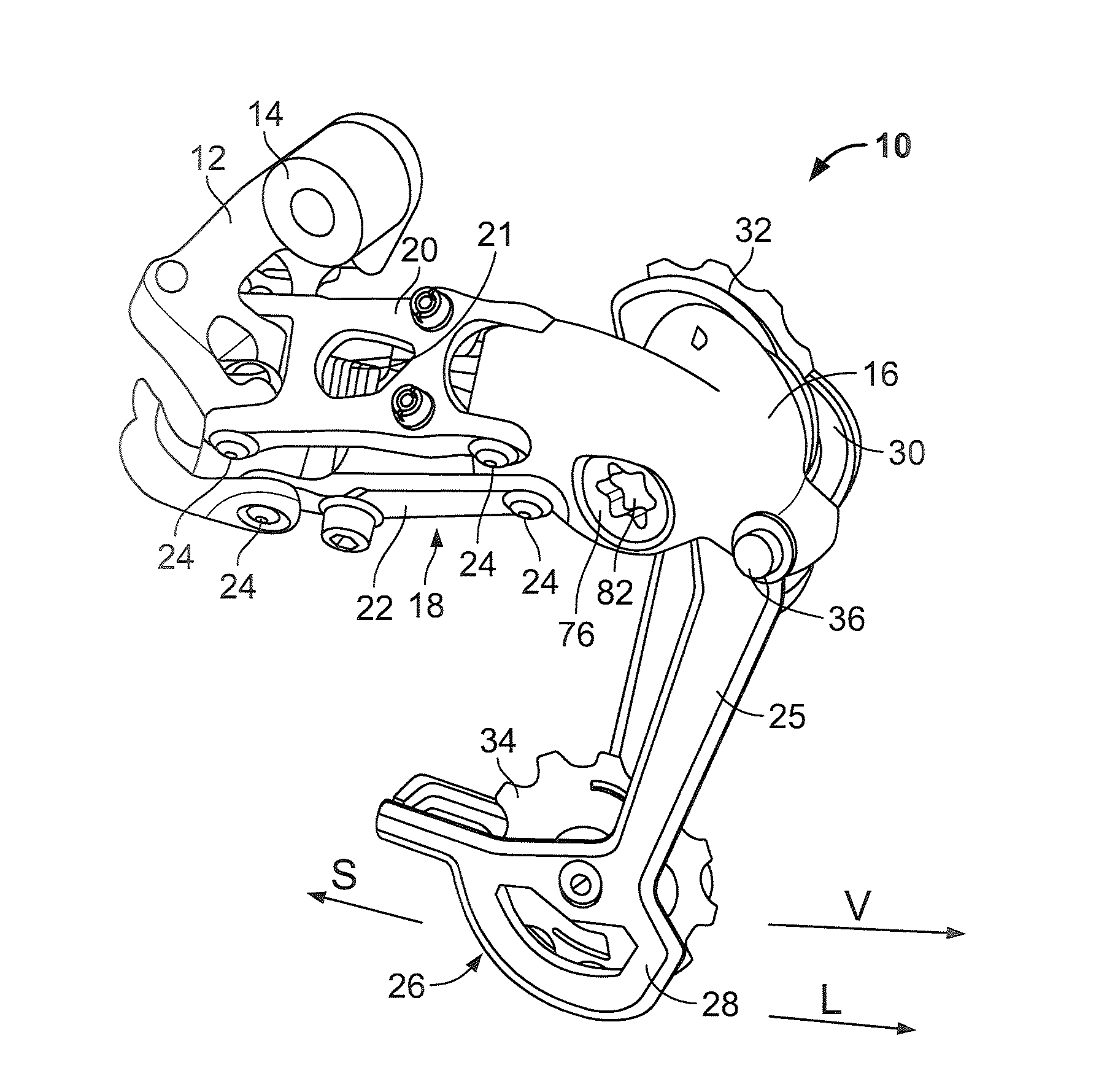
Figure 1 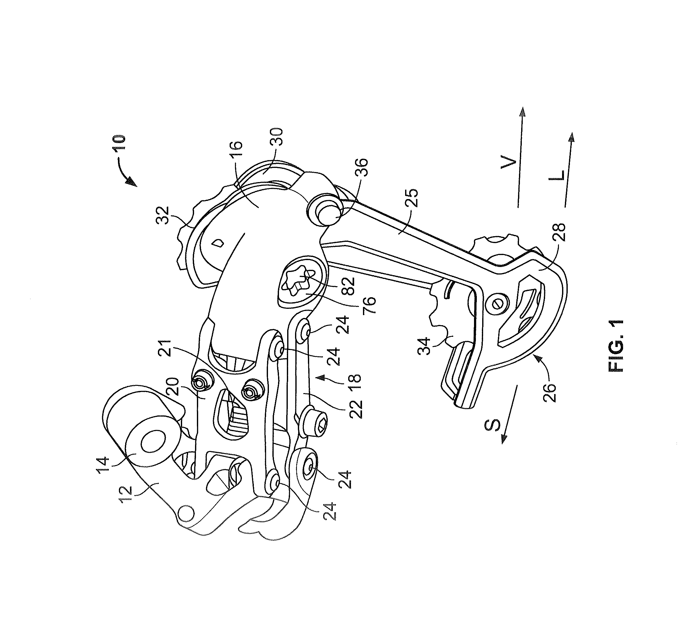
Figure 2 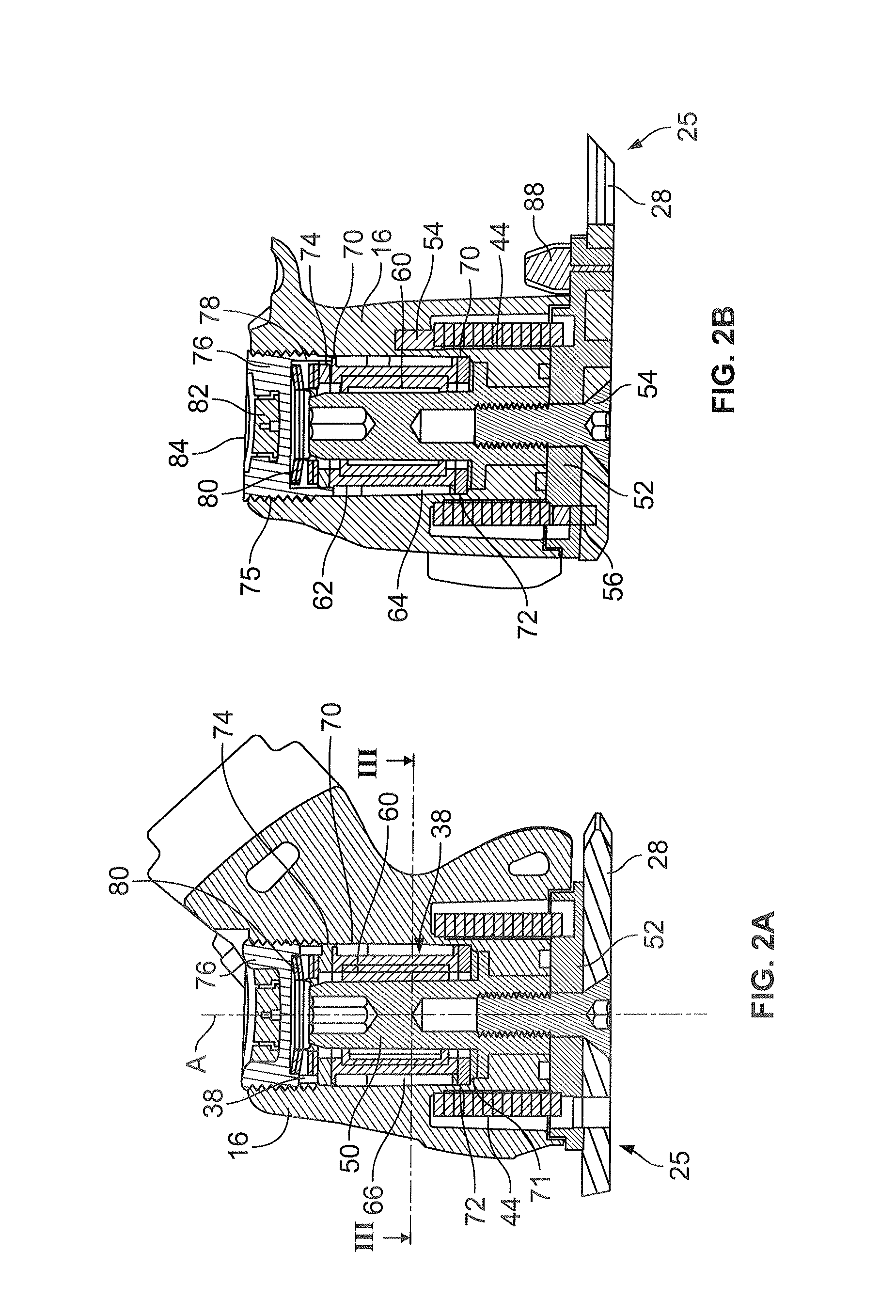
Figure 3
Abstract
Description
BACKGROUND OF THE INVENTION
[0001] The present invention generally relates to bicycle rear derailleurs and more particularly to a bicycle rear derailleur with a damper assembly.
[0002] It is known that a bicycle derailleur performs shifting operations by shifting the chain between a plurality of adjacent sprockets of a sprocket assembly of a bicycle. A further, also very important function of the derailleur is to ensure sufficient chain tension. For this purpose, a bicycle derailleur generally has the following structure. A base member is mounted on the bicycle. Furthermore, a movable member is movably coupled to the base member and a chain guide assembly is movably coupled to the movable member with respect to rotation about a rotational axis. The movable member is movable in the lateral (axial) direction to move the chain guide assembly between the sprockets of the sprocket assembly so that the chain may be shifted from an initial sprocket to a target sprocket. The chain guide assembl...
Examples
first embodiment
[0077]Further details of the derailleur are easily evident to a person skilled in the art from the related figures. A stop screw or a stop pin for limiting the pivot angle of the chain guide assembly is indicated with 88. It is also evident from the exploded views of FIGS. 4 and 5 how and in what sequence the components of the damper assembly 38 are to be accommodated in the cavity 66 of the movable member 16. The structure of the roller clutch assembly 60 to be provided, for example, can also be recognized in greater detail from FIG. 3, with the rotational shaft 50 as an inner clutch member, an outer clutch member 90 structured on the outside circumference in known manner, and a plurality of roller elements 92 between the two clutch members. The knurling of the friction washer 72 on its outside circumference, as already addressed, is indicated.
[0078]It should still be noted that the rotational shaft 50 has a tool engagement opening on its end opposite to the screw 54, which openin...
second embodiment
[0087]Possibilities with regard to the method of assembly of the components of the second embodiment, as addressed, are evident from the structure that can be seen in FIGS. 6a and 6b, and especially from the exploded views of FIGS. 8 and 9. It is possible to introduce the rotational shaft into the cavity 166 only later, after the screw element 176 has been screwed in, from the side of the movable member opposite to the chain guide, and then to screw it onto the cage plate 128 and the intermediate washer 152 by the screw 154.
[0088]FIGS. 10-14 show a third embodiment of the present invention. Once again, only the differences as compared with the embodiments previously described will be explained, and, for the remainder, reference is explicitly made to the above description. The same reference symbols as for the first embodiment are used for identical or analogous components, increased by 200, respectively.
[0089]The third embodiment clearly differs from the first and the second embodim...
third embodiment
[0093]However, alternatively, it can also be provided that the sleeves 262 and 264 of the third embodiment, as addressed, serve only for axial force transfer and—by means of their flange sections—for making the friction surfaces available, and accordingly, the roller clutch 250 has an inner clutch member in sleeve form, separate from the sleeves, which element stands in engagement with the sleeve elements 262 and 264 with press fit, for example, so that the sleeves are connected with the inner clutch member in torque-proof manner. This embodiment is compatible with the representation of the one-way clutch 260 in the sectional views of the FIGS., in which no inner structure of the one-way clutch itself can be seen. Corresponding one-way clutches are easily available as supplied components, as are the free-running sleeves without their own inner clutch member, as already addressed, which must be combined with a suitable rotational shaft.
[0094]According to the third embodiment, the fri...