
Position reference sensor
a technology of reference sensor and position sensor, which is applied in the direction of distance measurement, instruments, and using reradiation, etc., can solve the problems of unwanted reflection moving relative to the object, reflection disappearing, and problem of discrimination, so as to reduce the identification threshold, avoid false results, and optimize discrimination
Patent Information
- Authority / Receiving Office
- US · United States
- Patent Type
- Applications(United States)
- Current Assignee / Owner
- Publication Date
- 2018-01-11
- Estimated Expiration
- Not applicable · inactive patent
Smart Images
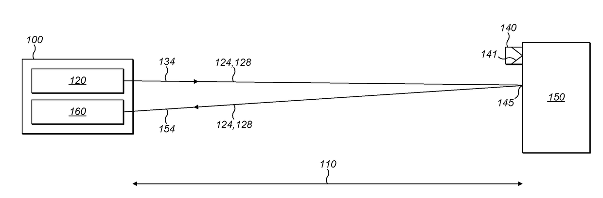
Figure 1 
Figure 2 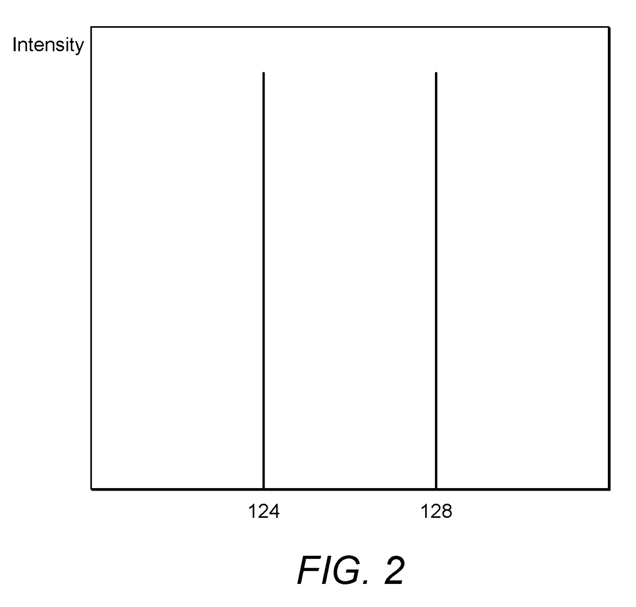
Figure 3
Abstract
Description
FIELD OF THE INVENTION
[0001] The present invention relates to a position reference sensor, for example, a position reference sensor for use in marine applications for determining the position of a vessel relative to an object. The present invention also relates to a position reference system.BACKGROUND OF THE INVENTION
[0002] Position reference sensors are used to determine position information indicating the position of a vessel relative to another object, such as another vessel or a fixed or floating platform, like an oil rig. Position information from a position reference sensor can be used by a dynamic positioning system to control the position of the vessel relative to the object. The dynamic positioning system may, for example, maintain a fixed relative position between the vessel and the object without the need for a physical connection between the vessel and the object to provide a virtual tether, for example, in a cable laying convoy. Alternatively, the dynamic positioning sys...
Examples
Embodiment Construction
[0159]FIG. 1 shows a position reference sensor 100 being used to determine a distance 110 between the position reference sensor 100 and a point 145 on object 150.
[0160]The position reference sensor 100 has a light source 120 which emits a beam of light 134 containing light at two different wavelengths—a first wavelength 124 and a second wavelength 128.
[0161]The beam 134 is directed towards the object 150. A selective retroreflector 140 is attached to the object 150. The selective retroreflector 140 has dielectric mirrors 141 which have been chosen to reflect the first wavelength 124 but not the second wavelength 128.
[0162]As well as the selective retroreflector 140, the object 150 has a variety of other reflective surfaces or elements (such as point 145) which can lead to an unwanted reflection 154 which does not come from the selective retroreflector 140. The unwanted reflection 154 is not a good choice for the position reference sensor 100 to use for determining the distance to th...