
Frequency-Dependent Damping Valve Arrangement
a frequency-dependent damping and valve arrangement technology, applied in the direction of spring/damper functional characteristics, vibration dampers, shock absorbers, etc., can solve the problems of difficult to find a vibration damper that can achieve this compromise, drive up production costs, and reduce the effect of damping
Patent Information
- Authority / Receiving Office
- US · United States
- Patent Type
- Applications(United States)
- Current Assignee / Owner
- Publication Date
- 2018-07-05
- Estimated Expiration
- Not applicable · inactive patent
Smart Images
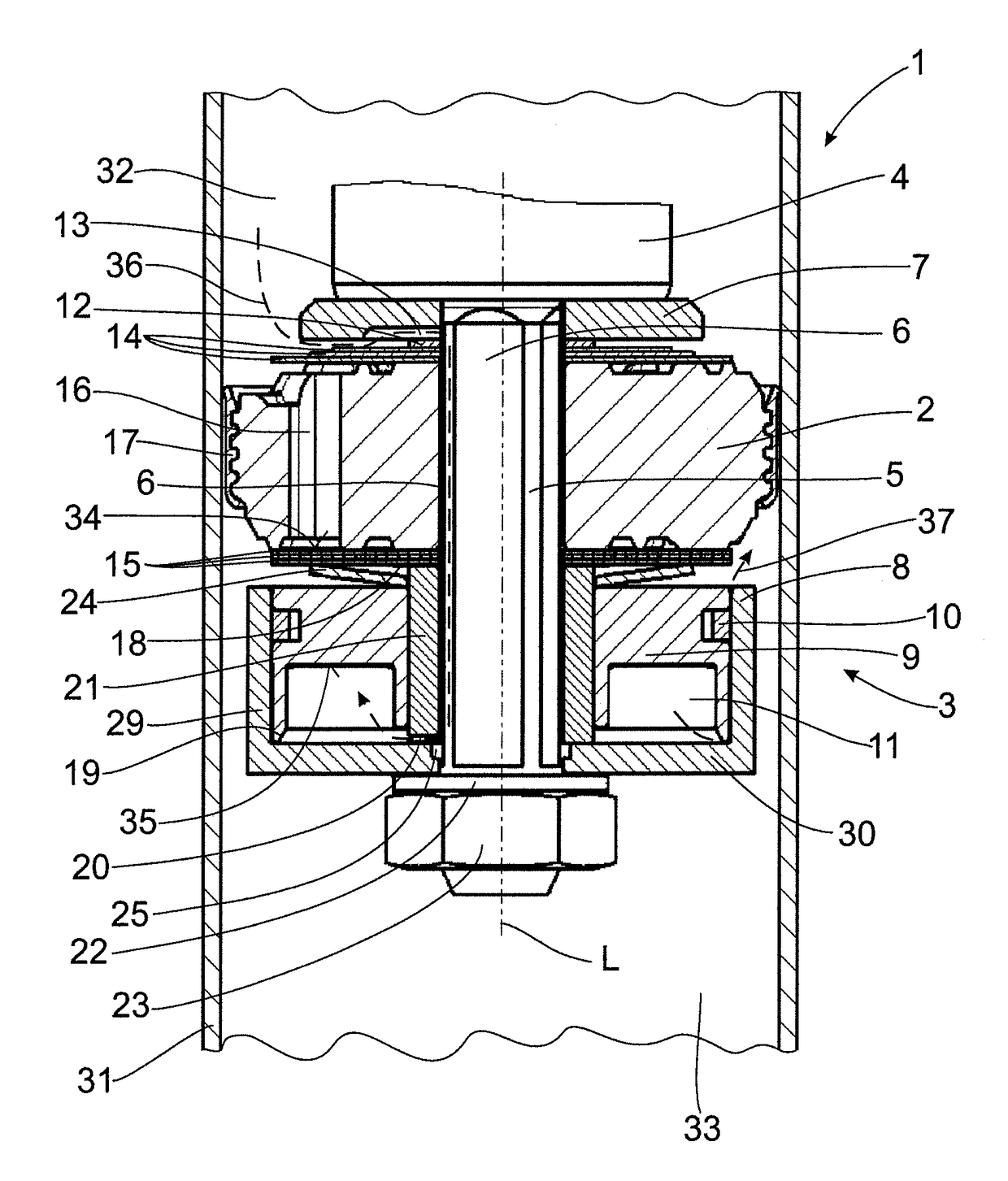
Figure 1 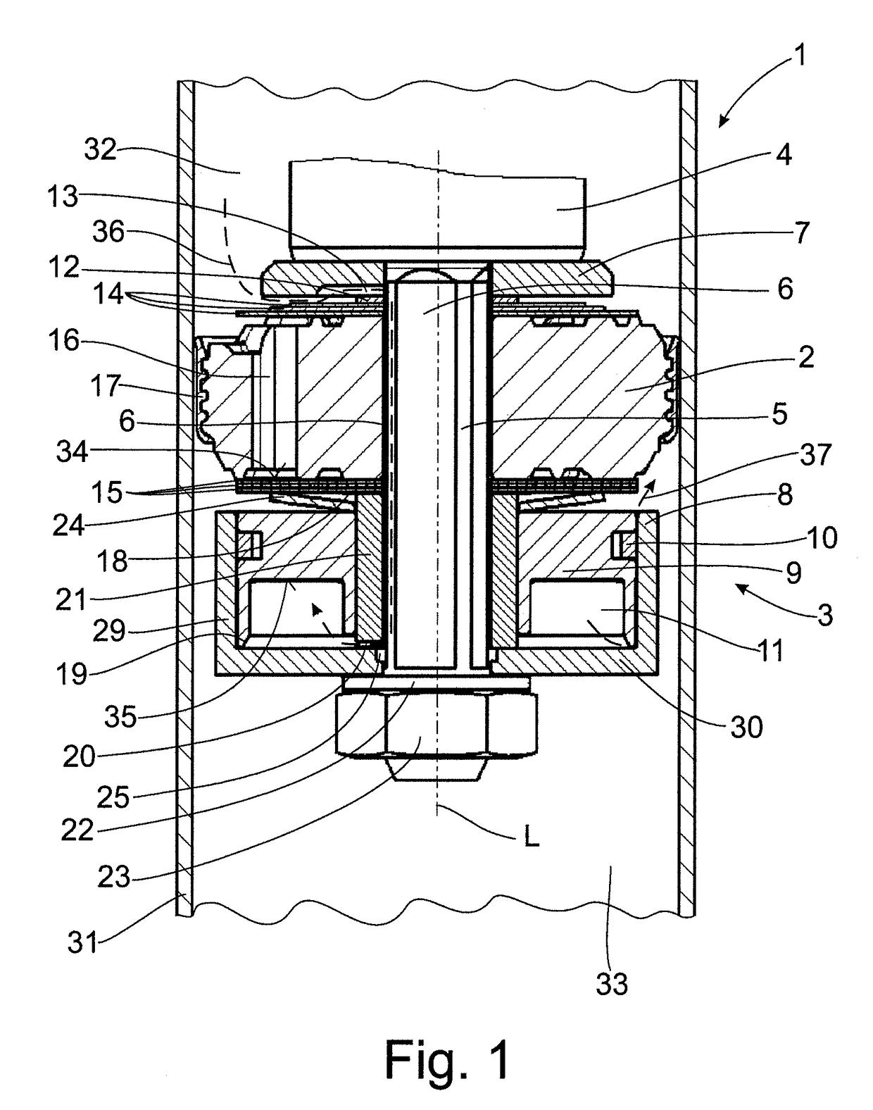
Figure 2 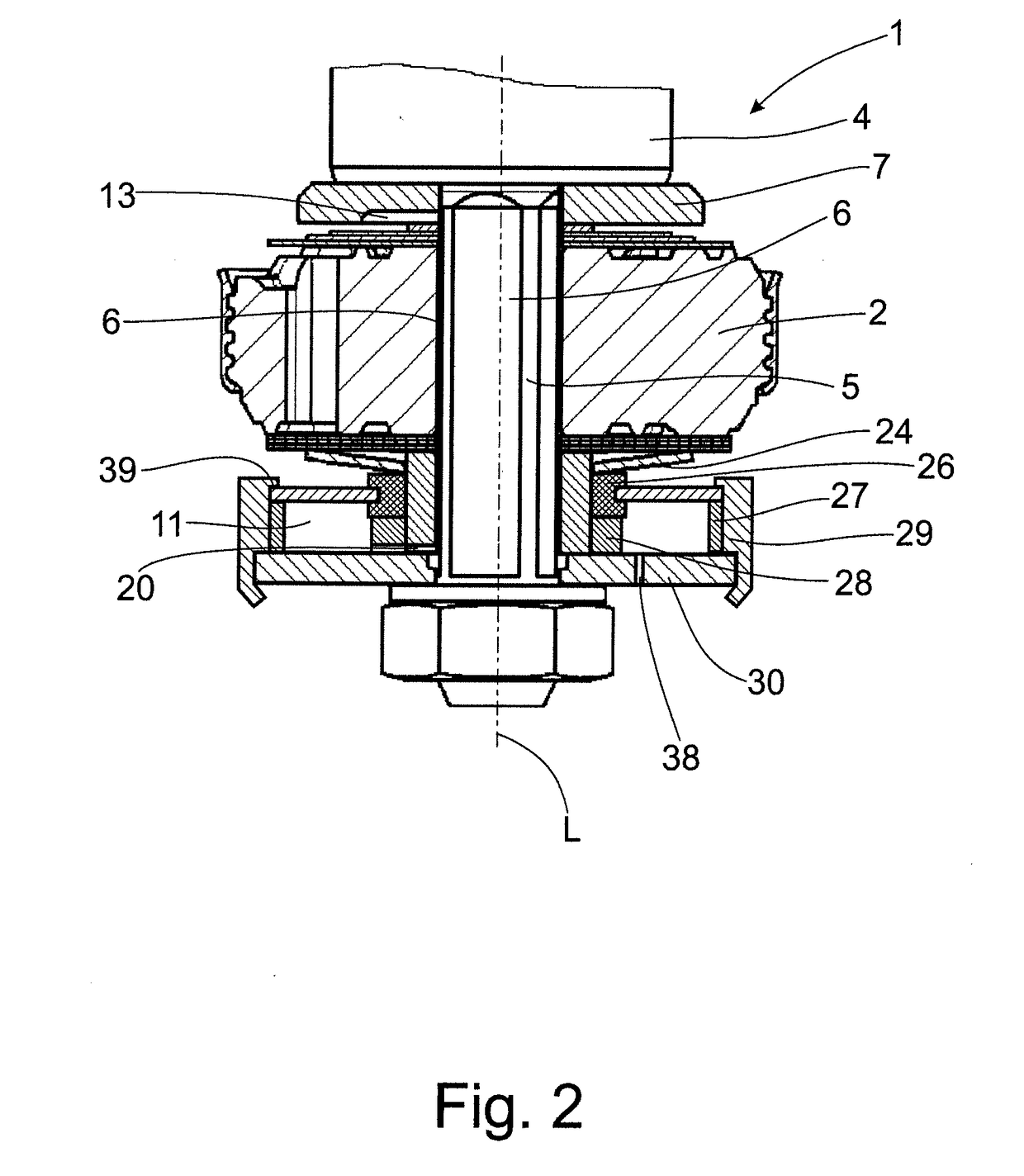
Figure 3
Abstract
Description
CROSS REFERENCE TO RELATED APPLICATIONS
[0001] This is a U.S. national stage of application No. PCT / EP2015 / 059017, filed on Apr. 27, 2015. Priority is claimed on German Application No. DE102014210705.9, filed Jun. 5, 2014, the content of which is / are incorporated here by reference.BACKGROUND OF THE INVENTION1. Field of the Invention
[0002] The invention is directed to a damping valve arrangement with a frequency-dependent damping force characteristic.2. Description of Prior Art
[0003] A vibration damper in a motor vehicle is provided to damp vibrations excited by the uneven road surface. In doing so, there must always be a compromise between driving safety and driving comfort. A vibration damper with a stiff damping valve arrangement having a high damping force characteristic is optimal for high driving safety. If greater comfort is demanded, the damping valve arrangement should be adjusted to be as soft as possible. It is very difficult to find this compromise in a vibration damper with ...
Examples
Embodiment Construction
[0021]FIG. 1 shows an exemplary construction variant of a damping valve arrangement with a frequency-dependent damping force characteristic.
[0022]FIG. 1 shows a piston rod 4, which has a piston rod tenon 5, as it is called. The piston rod tenon 5 is a portion of the piston rod 4 having a reduced diameter. The damping valve arrangement 1 in its entirety is threaded onto the piston rod tenon 5 and is axially clamped between a portion of the piston rod 4, which portion adjoins the piston rod tenon 5 and has a larger diameter than the piston rod 5, and fastener 23 shown in FIG. 1 as a piston rod nut.
[0023]As is shown in FIG. 1, the damping valve arrangement 1 comprises a damping piston 2 arranged inside a cylinder 31 filled with a damping fluid and which is axially secured to a piston rod 4. The damping piston 2 is outfitted with a piston seal 17 which radially seals it relative to the cylinder 31. The damping piston 2 which is fixed to the piston rod 4, is arranged to be axially displa...