
Cutting disk
Patent Information
- Authority / Receiving Office
- US · United States
- Current Assignee / Owner
- Publication Date
- 2020-02-06
- Estimated Expiration
- Not applicable · inactive patent
Smart Images
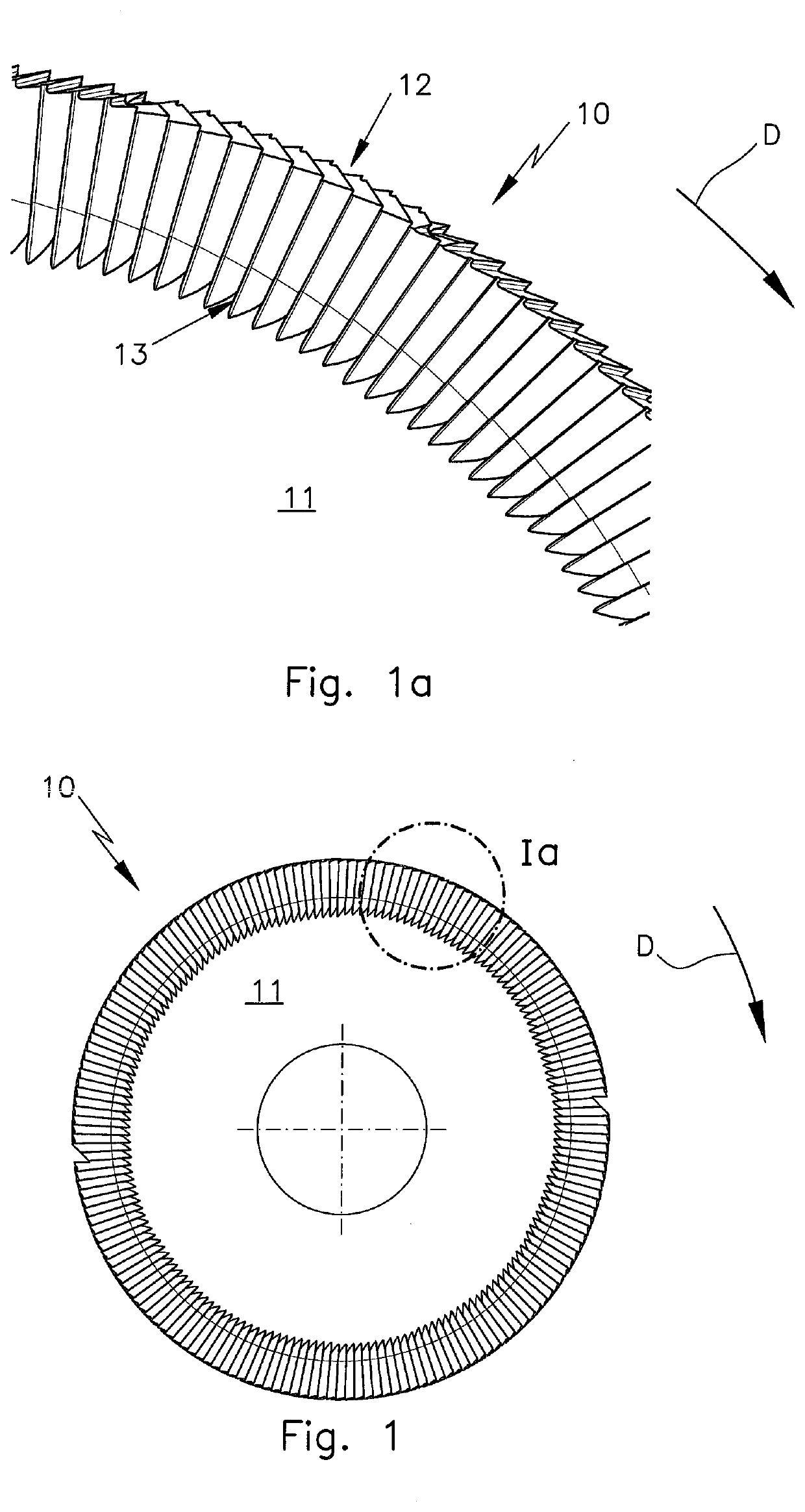
Figure 1 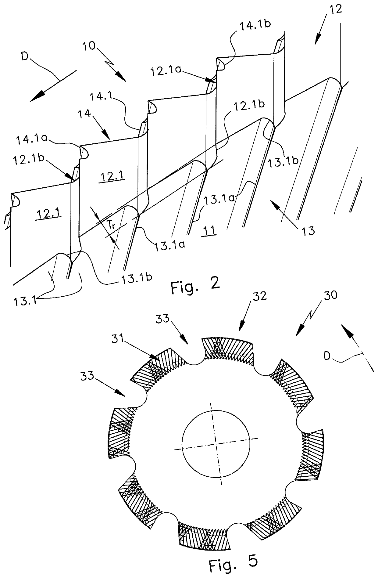
Figure 2 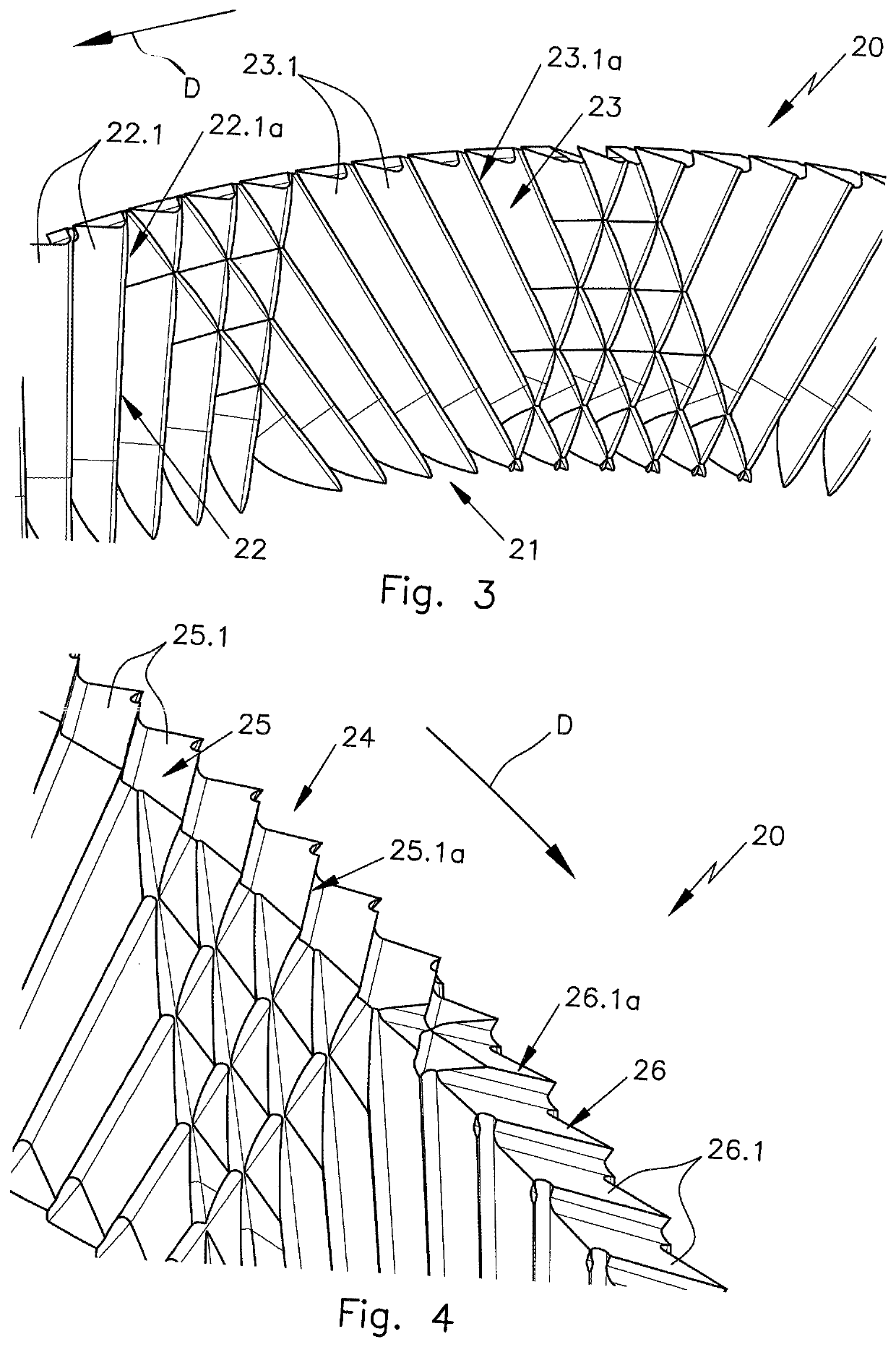
Figure 3
Abstract
Description
CROSS-REFERENCE TO RELATED APPLICATIONS
[0001] This application claims priority under 35 USC 119 of German Application No. 10 2018 118 959.1, filed on Aug. 3, 2018, the disclosure of which is herein incorporated by reference.BACKGROUND OF THE INVENTION
[0002] The invention is directed to a cutting disk for cutting and / or making grooves in workpieces, particularly workpieces of fiber-reinforced composite materials, with a disk-shaped base body which is provided at least in some areas with a circumferential toothing and with a flank toothing which is arranged at least in some areas at least on one lateral surface.
[0003] At the present time, various tools are used to machine composite structural component parts of fiber-reinforced composite materials. End mills of cemented carbide or cemented carbide saws or saws with soldered polycrystalline diamonds with conventional tooth geometries are used. It is also possible to use diamond-coated cutting disks with an indeterminate cutting geometry. ...
Examples
Embodiment Construction
[0025]The cutting disk 10 in FIGS. 1, 1a has a base body 11, a gapless circumferential toothing 12 and a gapless flank toothing 13. The flank toothing 13 is located in the outer radial area of the base body 11 and directly adjoins the circumferential toothing 12. The rotational direction of the cutting disk 10 and of the cutting disks in the other figures is indicated in each instance by an arrow D.
[0026]The detail view of the toothing of the cutting disk 10 in FIG. 2 looking at the opposite lateral surface shows that the base body 11 is also provided with a flank toothing 14 on its opposite lateral surface. The detail view in FIG. 2 further shows that the circumferential toothing 12 is formed by a plurality of circumferential teeth 12.1, and every circumferential tooth 12.1 has a main cutting edge 12.1a and two secondary cutting edges 12.1b. The flank toothing 13, on the other hand, is formed by a plurality of identical flank teeth 13.1 having a main cutting edge 13.1a and a second...