
System and method for operating a vehicle in a low transmission range
a transmission range and low-range technology, applied in mechanical equipment, external condition input parameters, transportation and packaging, etc., can solve the problems of insufficiently high driveline noise and vibration, and the disturbance of downshift driveline torque, so as to increase the propulsive torque, generate a substantial amount of driveline noise and vibration, and increase the level of driveline braking
Patent Information
- Authority / Receiving Office
- US · United States
- Patent Type
- Applications(United States)
- Current Assignee / Owner
- Publication Date
- 2020-12-17
Smart Images
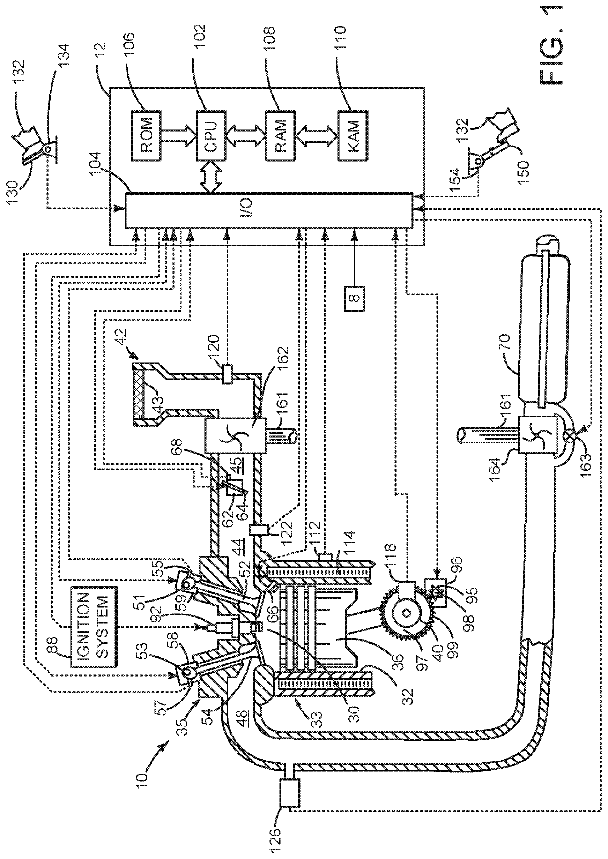
Figure 1 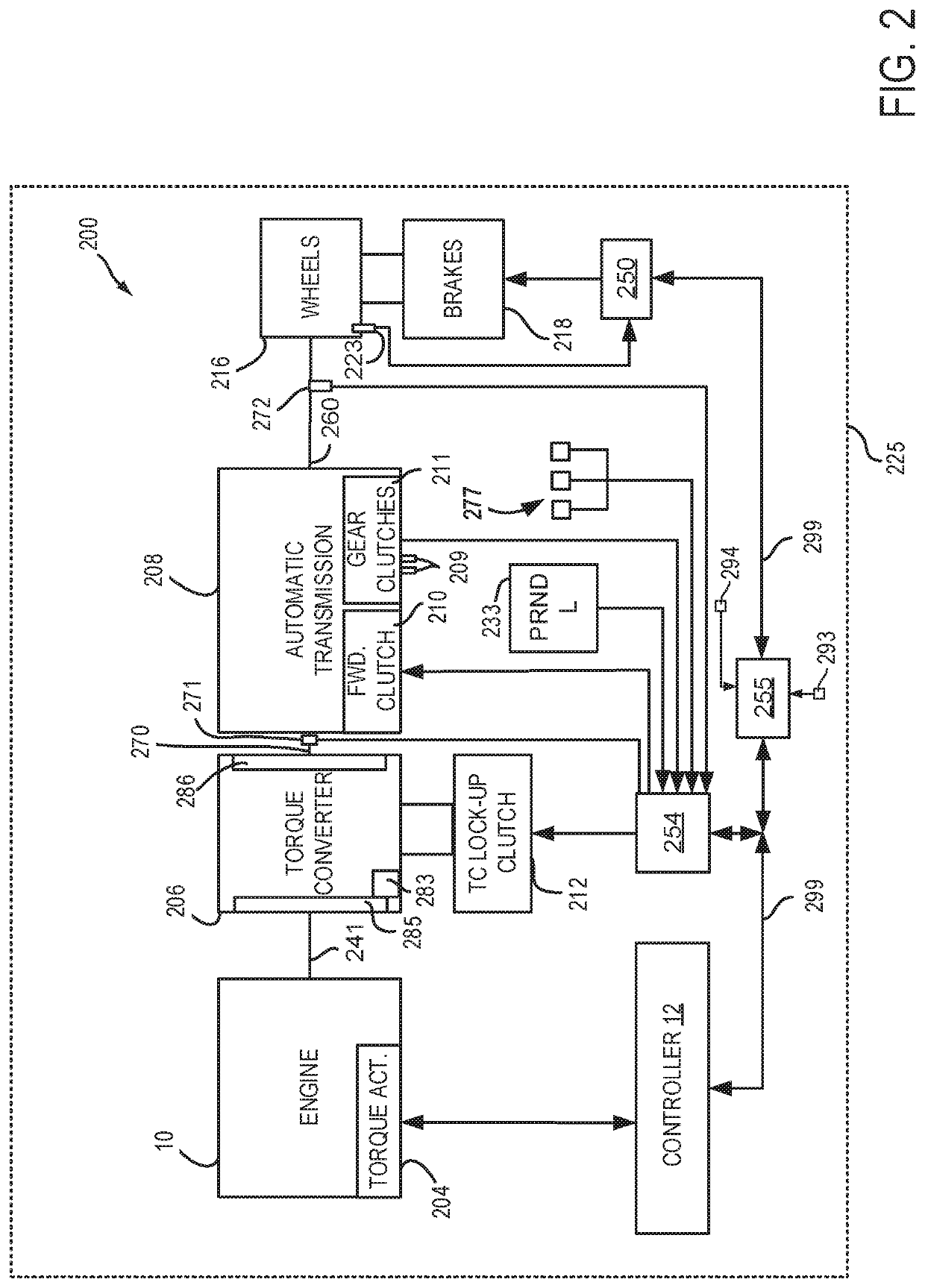
Figure 2 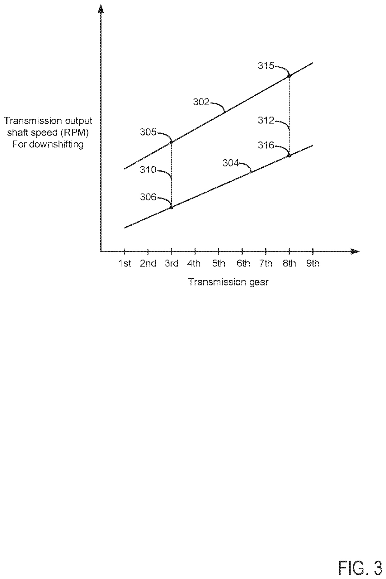
Figure 3
Abstract
Description
FIELD
[0001] The present description relates to systems and method for operating a transmission in a low range where driveline braking may be increased. The system and methods may be suitable for powertrains that only include an internal combustion engines as a torque source and powertrains that include an internal combustion engine and an electric machine as torque sources.BACKGROUND AND SUMMARY
[0002] A vehicle may include a transmission that may be put into a low gear range. The low gear range may provide higher levels of driveline braking during conditions where driver demand torque is low. The low gear range may also increase transmission output shaft speeds at which transmission gears are upshifted so that transmission gears may be held at engine speeds where engine torque production is greatest, thereby increasing the propulsive torque that may be delivered to a vehicle's wheels. If a human or autonomous driver engages the transmission in a low range while driver demand torque is...
Examples
Embodiment Construction
[0014]The present description is related to controlling a transmission of a driveline. The driveline may include an internal combustion engine as shown in FIG. 1. The internal combustion engine may be included in a driveline or powertrain of a vehicle as shown in FIG. 2. Gears of the transmission may be engaged during gear downshifts according to higher and lower engagement speeds as shown in FIG. 3. Several prophetic transmission downshifts are shown in FIG. 4. Finally, a method for shifting a transmission is shown in FIG. 5.
[0015]Referring to FIG. 1, internal combustion engine 10, comprising a plurality of cylinders, one cylinder of which is shown in FIG. 1, is controlled by electronic engine controller 12. Engine 10 is comprised of cylinder head 35 and block 33, which include combustion chamber 30 and cylinder walls 32. Piston 36 is positioned therein and reciprocates via a connection to crankshaft 40. Flywheel 97 and ring gear 99 are coupled to crankshaft 40. Optional starter 96...