
Acoustic filter for a coaxial electro-acoustic transducer
a coaxial electro-acoustic transducer and filter technology, applied in the field of loudspeakers, can solve the problems of prone to mismatch in coaxial alignment dip in frequency response, etc., and achieve the effect of restoring the response perceived by the listener, reducing cross-talk, and reducing the cost of operation
Patent Information
- Authority / Receiving Office
- US · United States
- Current Assignee / Owner
- Publication Date
- 2021-09-23
Smart Images
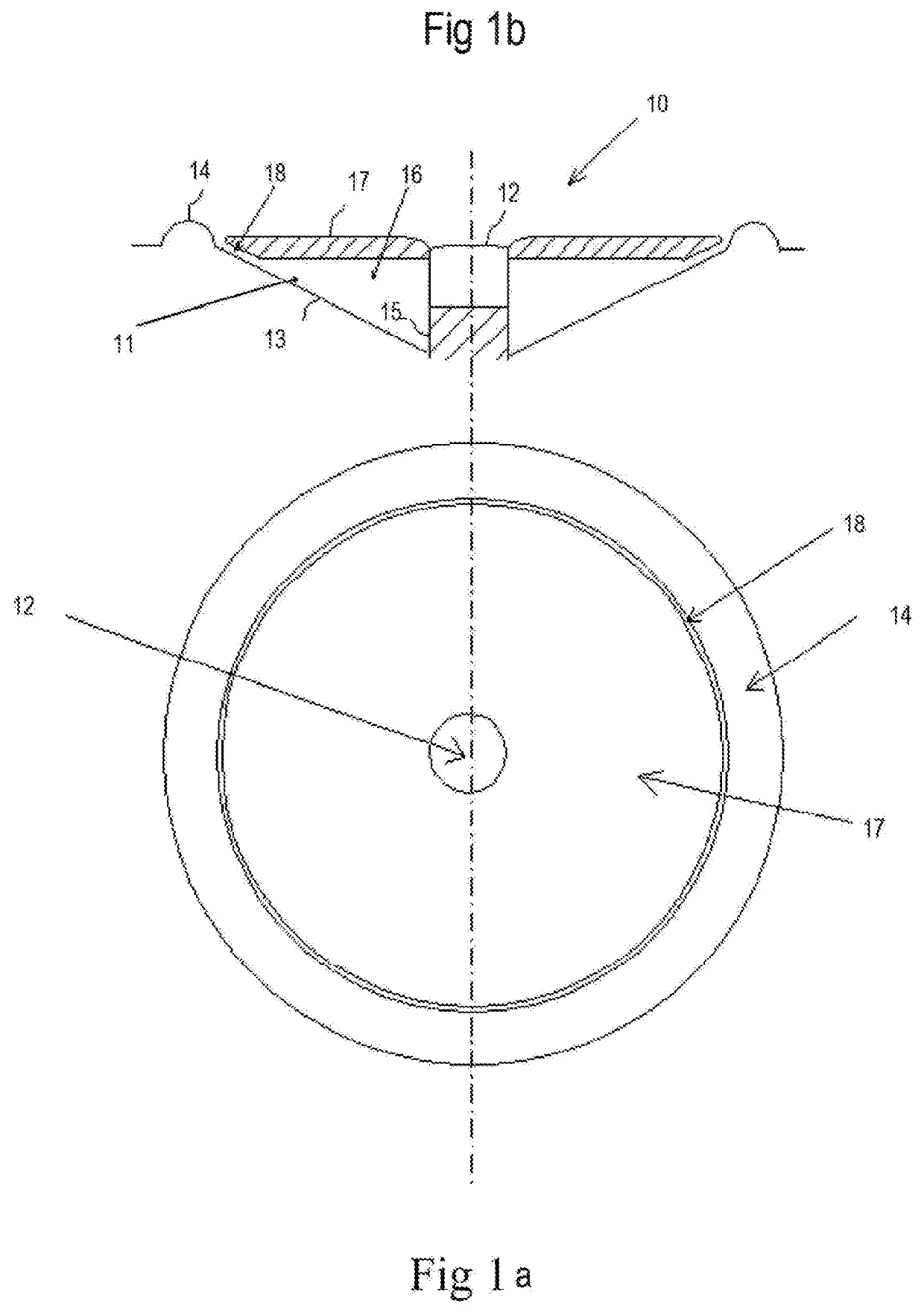
Figure 1 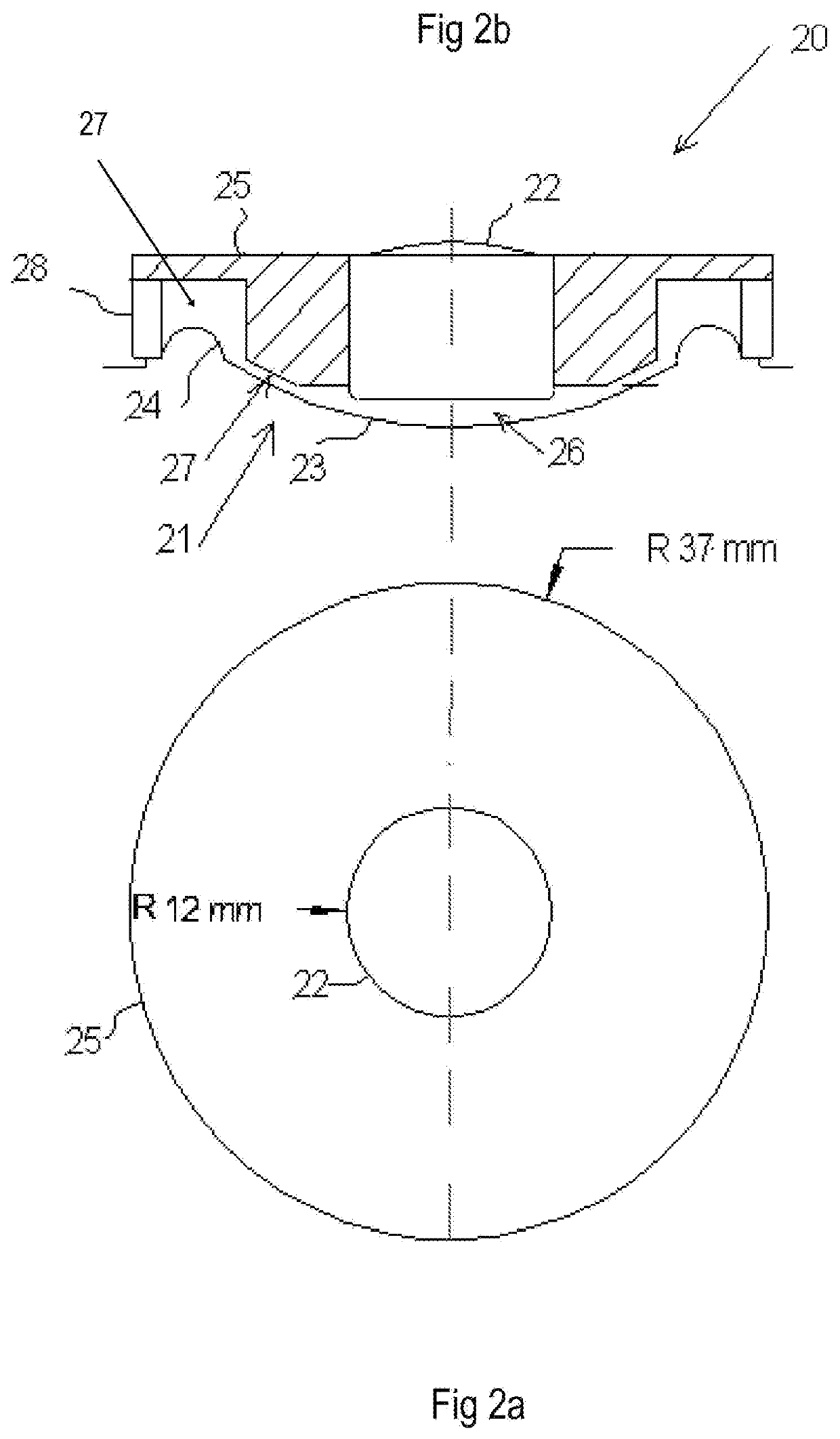
Figure 2 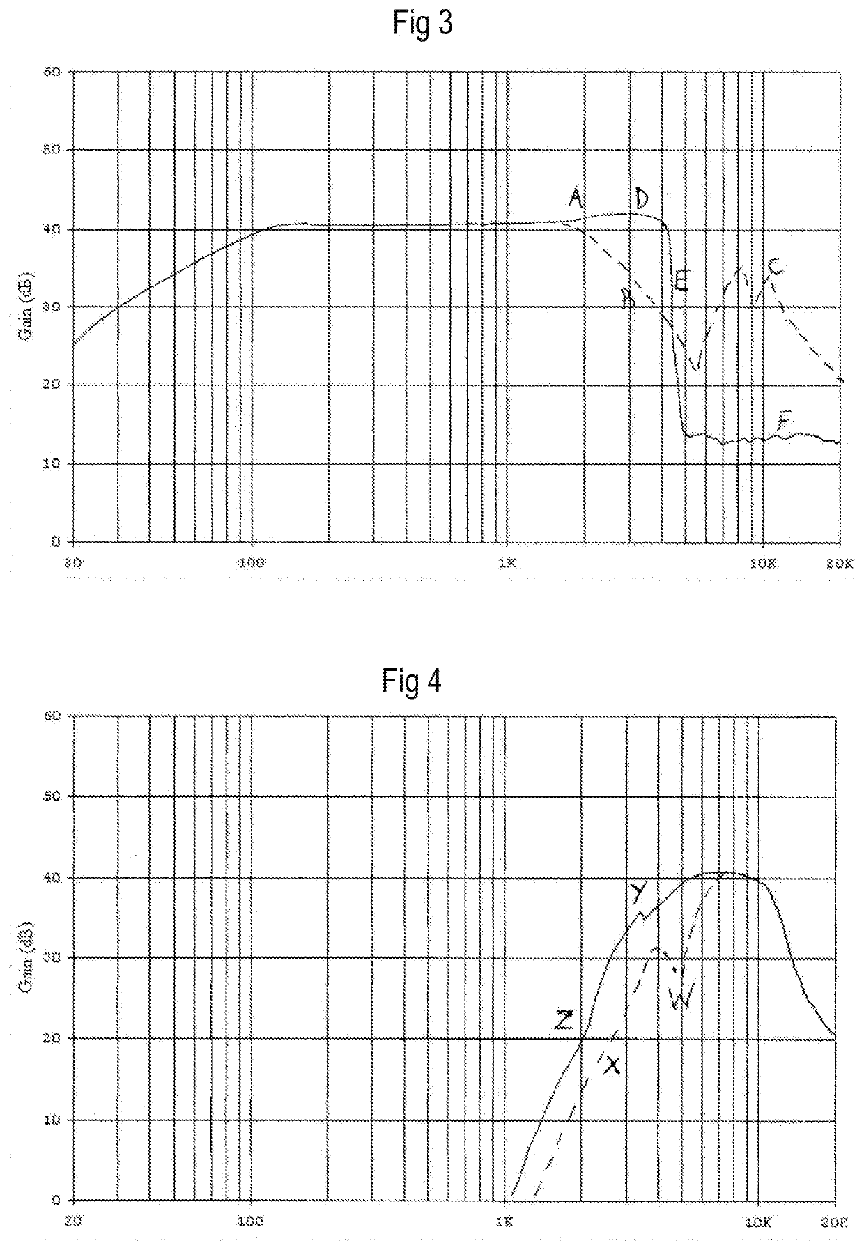
Figure 3
Abstract
Description
TECHNICAL FIELD
[0001] The present invention relates to loudspeakers and in particular to an acoustic filter for a coaxial electro-acoustic transducer.DEFINITIONS
[0002] Throughout this specification “electro-acoustic driver” or “driver” includes a loudspeaker transducer. “Coaxial driver” includes two or more drivers in a composite or substantially coaxial alignment or structure. “Loudspeaker” includes one or more drivers mounted in an enclosure or baffle. “Piston range” includes a range of frequencies wherein the corresponding wavelength is greater than the circumference of a driver. The upper limit of piston range is sometimes defined as the frequency at which ka=1 wherein k=wave number (2 pi / wavelength) and a=piston radius. Circumference of a driver includes its effective diameter as understood in the art multiplied by pi.
[0003] A crossover defines the point or region in which one frequency band interfaces with another. Accordingly, the adjoining frequency bands may be referred to as ...
Examples
Embodiment Construction
[0032]Preferred embodiments of the present invention will now be described in conjunction with the accompanying drawings. The attached drawings are intended to show the breadth of scope of the present invention. In particular FIGS. 1a and 1b show a pedestal mounted tweeter as is common in the art and FIGS. 2a and 2b show an independently mounted tweeter.
[0033]FIGS. 1a and 1b show coaxial transducer 10 comprising a relatively low frequency driver such as a mid-range driver 11 and a relatively high frequency driver such as a tweeter 12. The cone 13 of mid-range driver 11 is shown together with its surround 14. The remaining parts of mid-range driver 11 are not shown as they do not form part of the acoustic crossover filter. A person skilled in the art may readily identify mid-range driver 11 from the parts shown in FIGS. 1a and 1b.
[0034]Tweeter 12 is shown mounted on pedestal 15 which passes through cone 13 of mid-range driver 11. Helmholtz resonator chamber 16 is formed between baff...