
Surface light source device of side light type
a technology of surface light source and side light, which is applied in the direction of lighting and heating equipment, instruments, machines/engines, etc., can solve the problems of unsatisfactory bright lines along both sides, and achieve the effect of preventing the generation of bright lines along the side edges of the emission surfa
Patent Information
- Authority / Receiving Office
- US · United States
- Patent Type
- Patents(United States)
- Current Assignee / Owner
- Publication Date
- 2002-06-18
- Estimated Expiration
- Not applicable · inactive patent
Smart Images
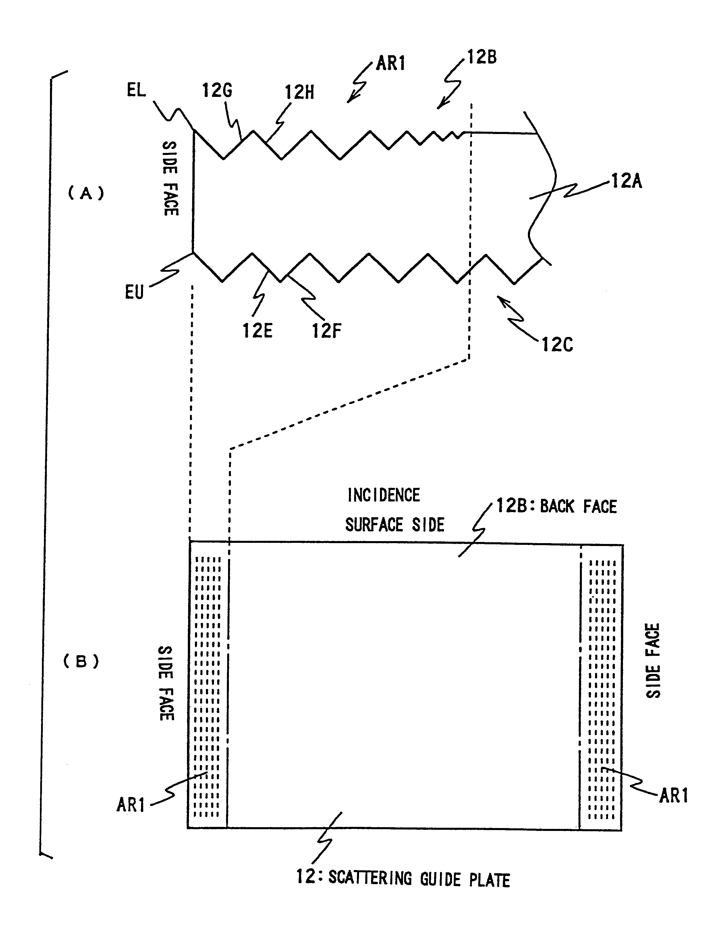
Figure 1 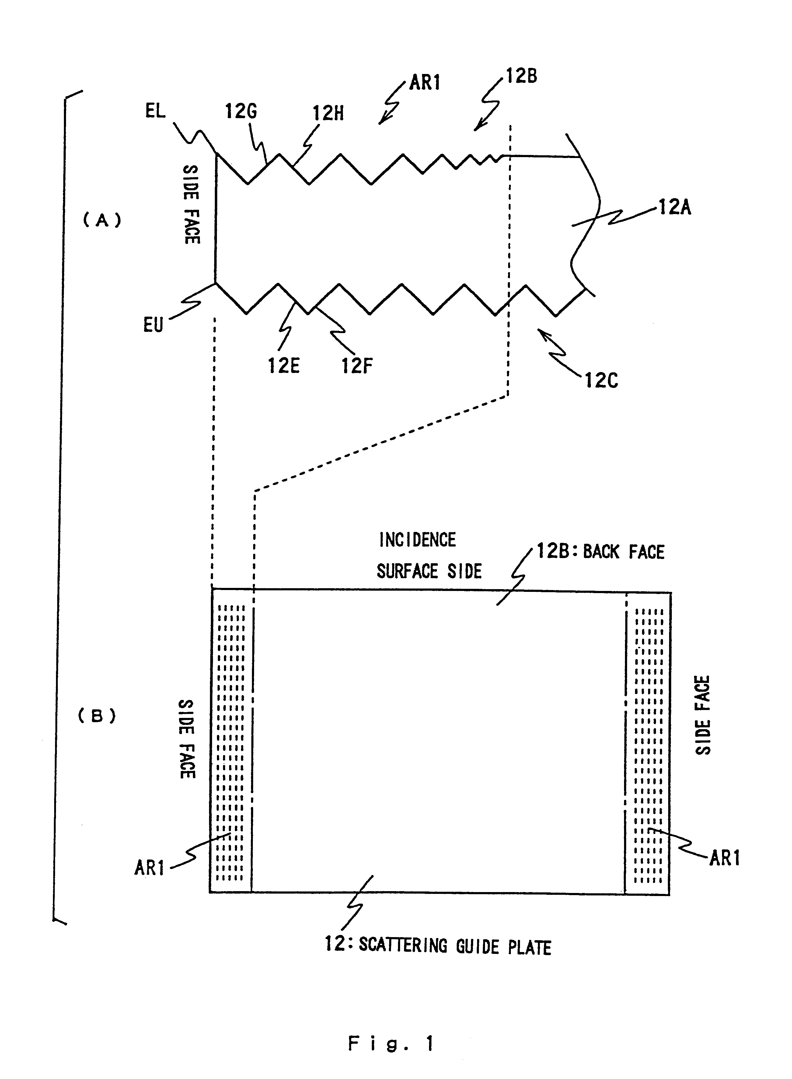
Figure 2 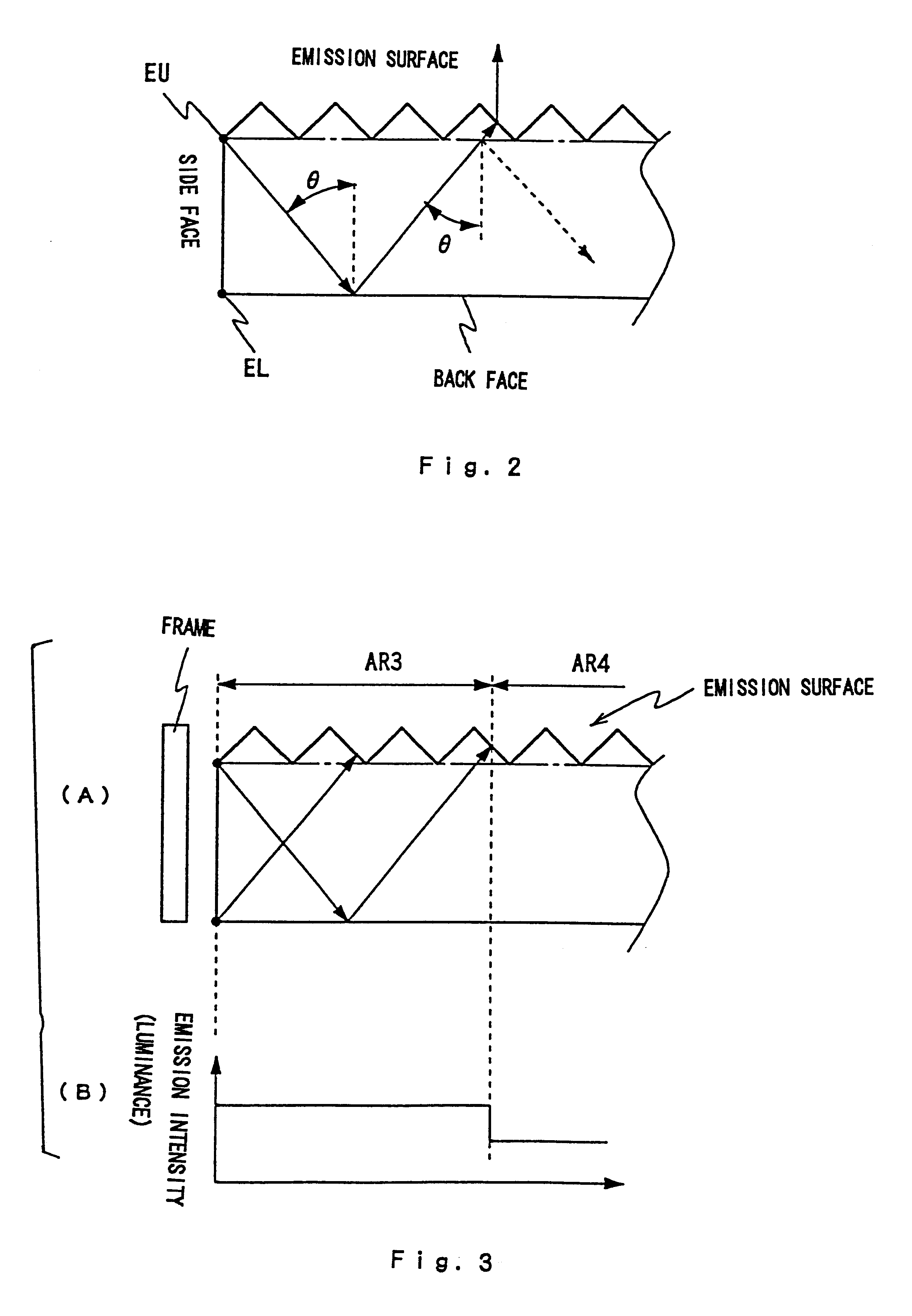
Figure 3
Abstract
Description
The present invention relates to a surface light source device of side light type, and more particularly to a technique for improving quality of illuminating light in the device. The surface light source device according to the present invention is applied to, for instance, backlighting of a liquid crystal display.RELATED ARTIt is well known that a surface light source device of side light type is applied to backlighting of a liquid crystal display. The surface light source device supplies illuminating light from the back face of a liquid crystal panel. This arrangement is suitable for making the overall shape of the display thinner.In general, a surface light source device of side light type uses a rod-shaped light source, such as a cold cathode tube, as a primary light source. The rod-shaped light source is provided on a side of a guide plate (plate-like guide body). Illuminating light, emitted from the primary light source, is guided inside the guide plate through an incidence en...
Examples
Embodiment Construction
(1) Embodiment
FIG. 1 illustrates features of a scattering guide plate 12 used in the present invention, showing a plan view (A) of under surface 12B and a side view (B) from an incidence surface (incidence end surface) 12A. The surface light source device of side light type according to the present invention replaces the guide plate 2 of the device shown in FIG. 8 and FIG. 9 with a new scattering guide plate 12.
The following explanation centers on structure and effect of the scattering guide plate 12, with reference to FIG. 8 and FIG. 9 as necessary. In FIG. 8 and FIG. 9, reference symbols relating to the scattering guide plate 12 are indicated in brackets.
As shown in FIG. 1, the scattering guide plate 12 (hereinafter, guide plate 12), which is generally wedge-shaped, preferably comprise the same type of material as the scattering guide body 2 (see FIG. 8 and FIG. 9). The matrix comprises, for instance, polymethyl-methacrylate (PMMA) and a great number of light-permeable particles, ...