
Stationary coil oscillator scanning system
a scanning system and torsion oscillator technology, applied in the field of scanning systems, can solve the problems of relatively minor heat, electrical or material breakdown problems, especially problematic structure, etc., and achieve the effects of improving performance, small size, and lack of expens
Patent Information
- Authority / Receiving Office
- US · United States
- Patent Type
- Patents(United States)
- Estimated Expiration
- Not applicable · inactive patent
Smart Images
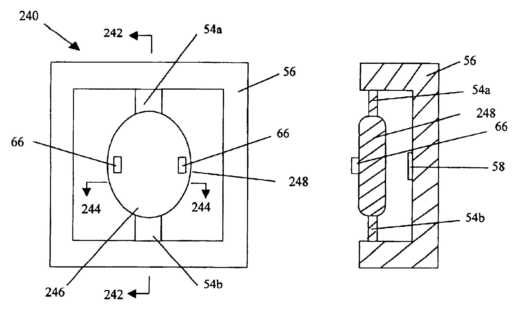
Figure 1 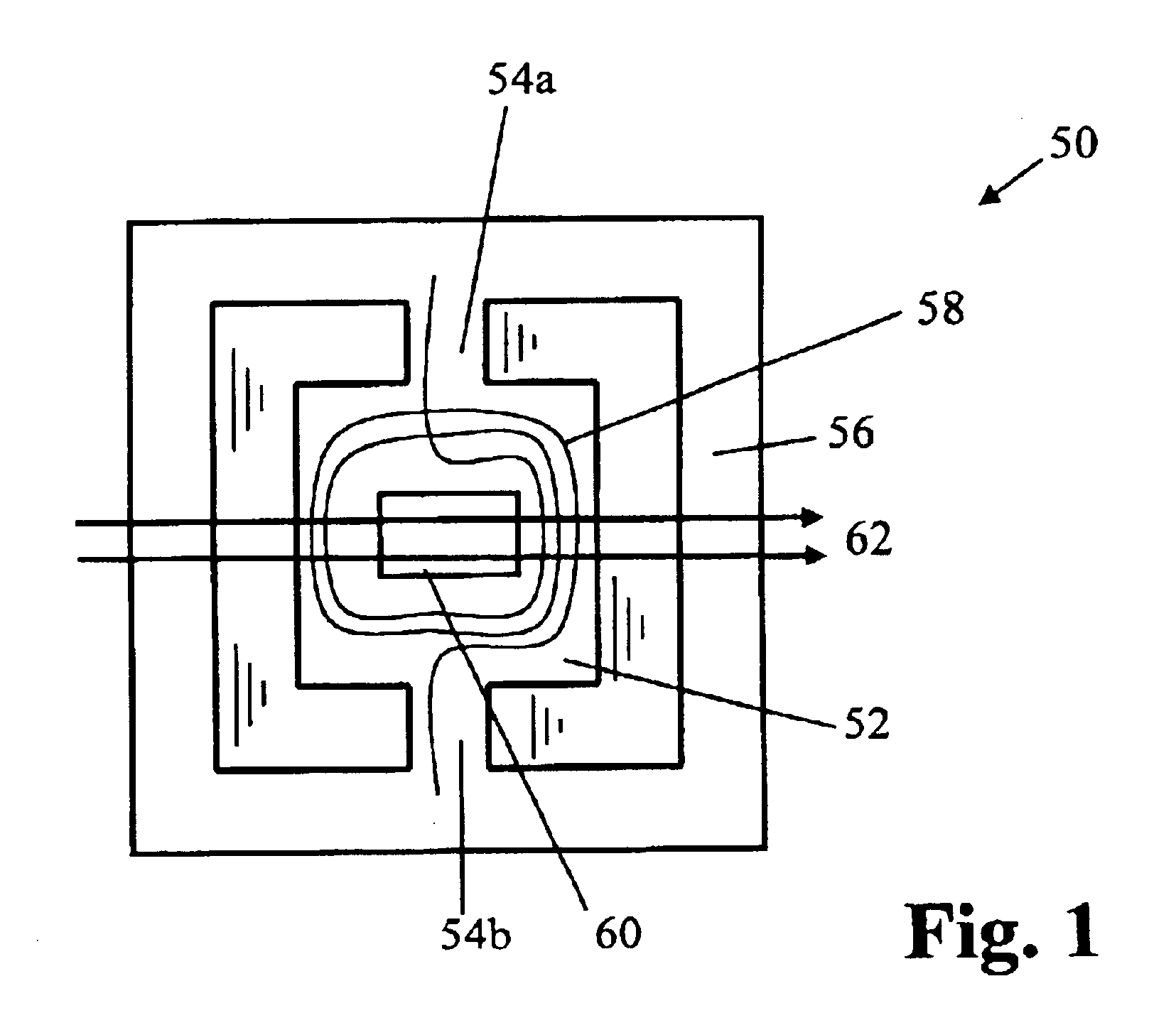
Figure 2 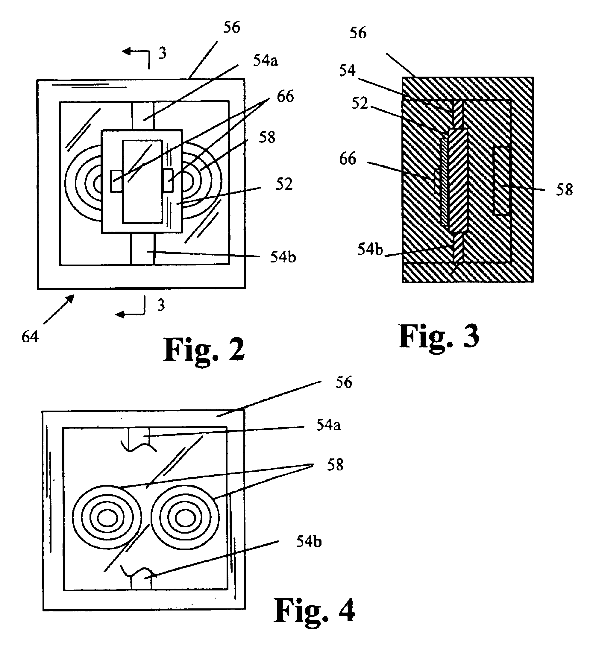
Figure 3
Abstract
Description
FIELD OF THE INVENTIONThe present invention is generally directed to scanning systems. More particularly, the invention is directed to a stationary coil torsion oscillator scanning system.BACKGROUND OF THE INVENTIONTorsion oscillators are known, although not widely employed. U.S. Pat. No. 3,803,637 to Martin et al., U.S. Pat. No. 4,762,994 to Byerly et al., U.S. Pat. No. 5,542,956 to Nakagawa et al., U.S. Pat. No. 5,543,956 to Nakagawa et al., and U.S. Pat. No. 5,767,666 to Asada et al. are illustrative. Problems associated with torsion oscillators include bulk associated with the materials used for the springs, magnets and coils; frequency drift; and instability. In general, these problems and others have prevented or discouraged use of torsion oscillators in applications such as optical systems. Current conventional wisdom provides that torsion oscillators are inferior to rotating mirror devices and are unacceptable for use in scanning devices such as commercial or desktop laser p...
Examples
Embodiment Construction
Preferred embodiments of the present invention utilize a torsion oscillator. The torsion oscillator 50 of FIG. 1 comprises a central generally rectangular plate 52 suspended by two extensions 54a, 54b of the material of plate 52. The plate 52 is generally symmetrical about its axis of oscillation. Extensions 54a, 54b are integral with a surrounding frame 56. Typically, the plate 52, extensions 54a, 54b and frame 56 are cut or etched from a single silicon wafer. A coil 58 of conductive wire and a mirror 60 or similar reflective surface are placed on the central plate. The mirror may be a smooth or polished surface on the silicon plate 52, since silicon itself is about sixty percent reflective Typically the mirror is a deposited layer of gold (or other material) on the smooth silicon substrate. Since the reflectivity of the silicon is wavelength dependent (falling off rapidly about 1 micron wavelength), a deposited mirror is typically used, or the raw silicon can be used without a mir...