

Method and device for detecting deposit in a conduit
a technology of deposit detection and conduit, which is applied in the direction of testing water, mechanical equipment, instruments, etc., can solve the problems of clogging pipes, affecting production, and expensive techniques, and affecting the quality of the product,
Patent Information
- Authority / Receiving Office
- US · United States
- Current Assignee / Owner
- Publication Date
- 2005-05-03
- Estimated Expiration
- Not applicable · inactive patent
Smart Images
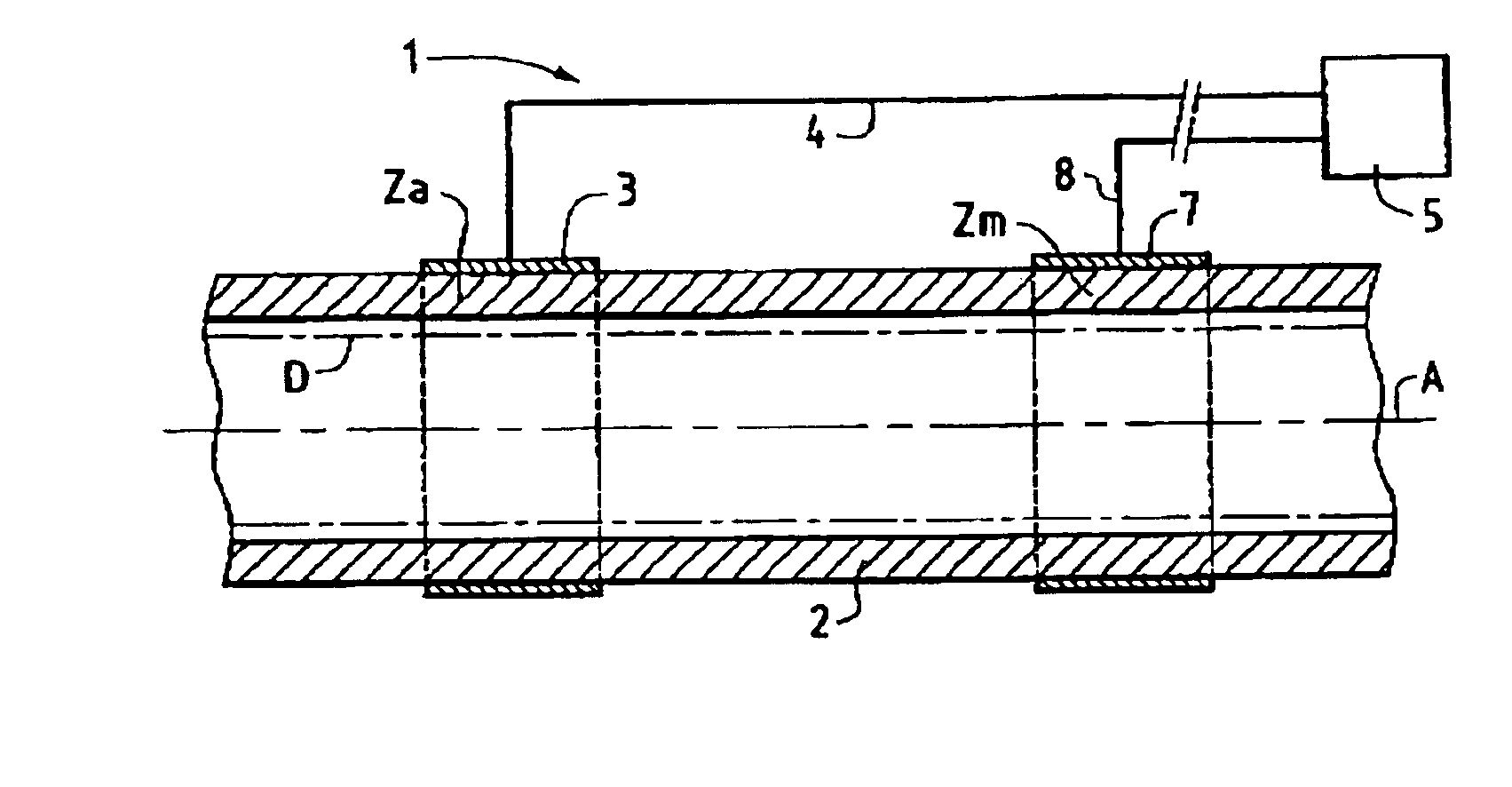
Figure 1 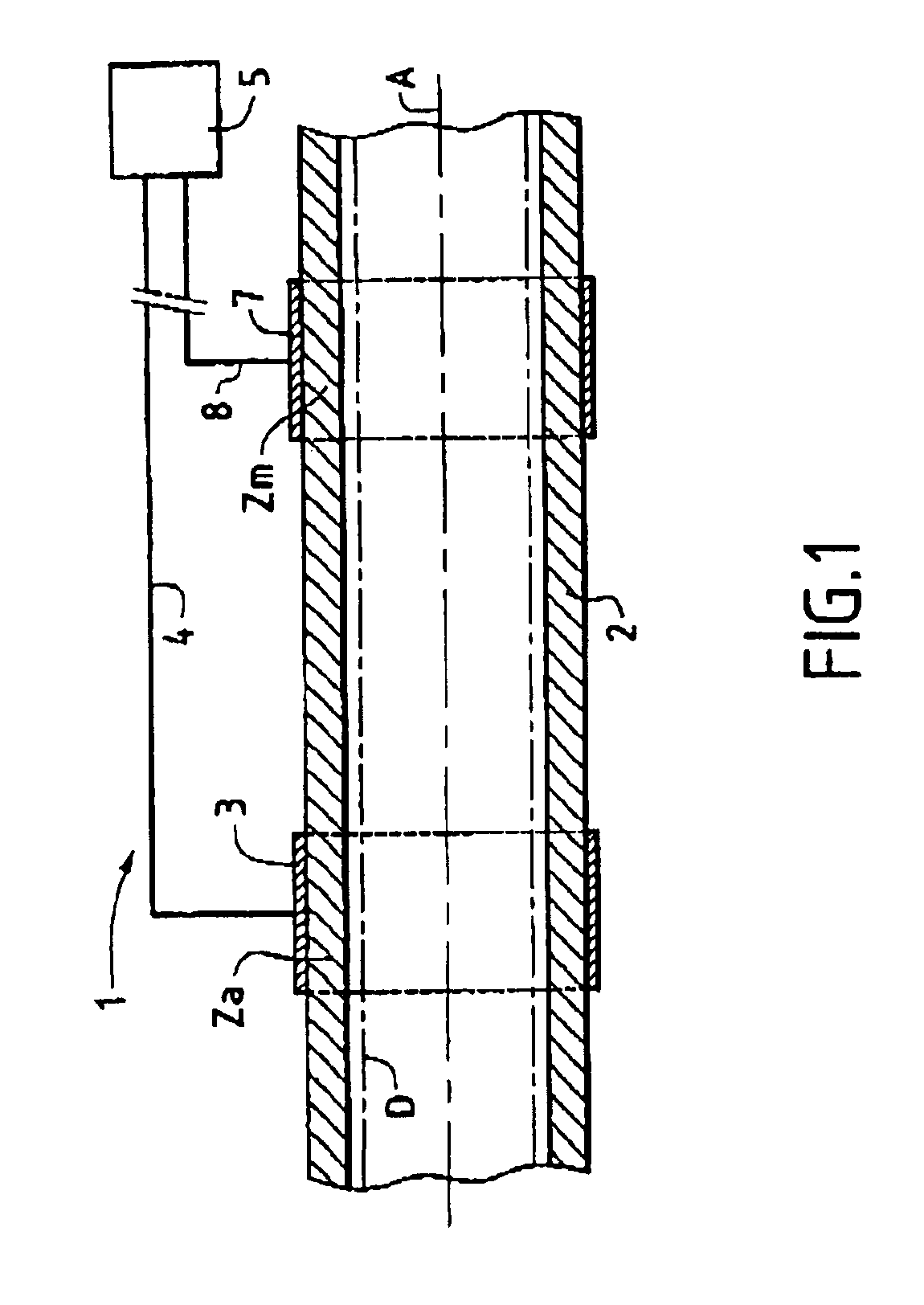
Figure 2 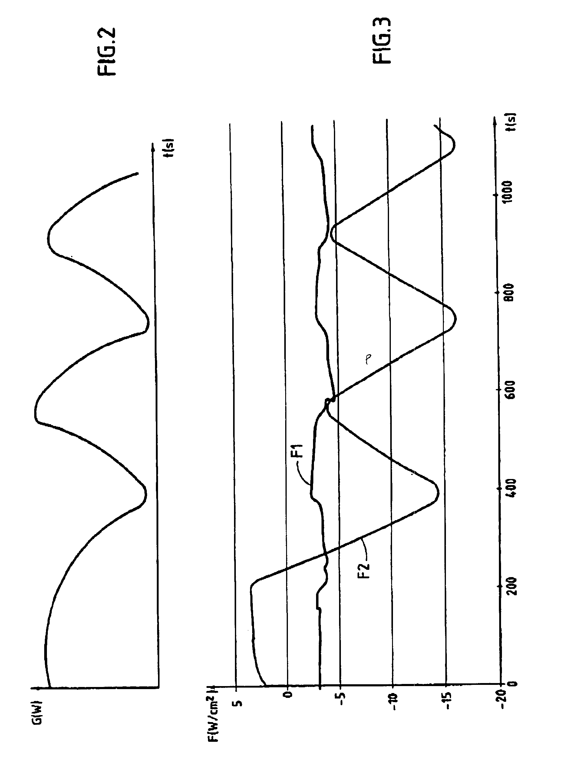
Figure 3
Abstract
Description
FIELD OF THE INVENTION
[0004] The present invention relates to the field of detecting a deposit or a solid phase liable to form in a pipe for transporting a fluid, in the general sense.
[0005] A preferred application of the invention lies in avoiding the risks of clogging in fluid transport pipes, and in particular in pipes for transporting multiphase petroleum fluids.
[0006] It is known that such multiphase petroleum fluids can lead to the formation of a solid phase such as hydrates, paraffins, asphaltenes, or other mineral deposits. The solid phase can be deposited at one or more locations in the pipe, thereby reducing flow rate to such an extent as to disturb hydrocarbon transport completely.
[0007] Present economic circumstances are encouraging operating companies to significantly reduce investment and operating costs, in particular, by improved control and by seeking to eliminate any risk of such a solid phase being deposited, both in processing installations and in installations for t...
Examples
Embodiment Construction
[0028]As can be seen more clearly in FIG. 1, the installation 1 of the invention is adapted to detect a deposit, in the general sense, that might form inside a fluid transport pipe 2, in particular a petroleum transport pipe. In conventional manner, transporting multiphase petroleum fluids runs the risk of forming a deposit or a solid phase such as hydrates, paraffins, asphaltenes, or mineral deposits inside the pipe, as represented diagrammatically by reference D.
[0029]In accordance with the invention, the installation 1 has at least one source 3 for producing a thermal gradient G. Such a production source 3 is for mounting in an “active” zone Za of the outside surface of the pipe 2. It should be considered that the source 3 delivers or extracts a determined quantity of heat over a selected zone of the pipe 2 by any suitable means. By way of example, the quantity of heat delivered to the pipe 2 can be produced by the Joule effect, the Pelletier effect, or the Seebeck effect. In an ...