
Active current sharing circuit
a current sharing and active technology, applied in the direction of power conversion systems, dc-dc conversion, dc source parallel operation, etc., can solve the problems of reducing the efficiency of the converter, and not providing any active current sharing, so as to achieve the effect of efficient supply of high power to a common load
Patent Information
- Authority / Receiving Office
- US · United States
- Patent Type
- Patents(United States)
- Current Assignee / Owner
- Publication Date
- 2005-05-17
- Estimated Expiration
- Not applicable · inactive patent
Smart Images
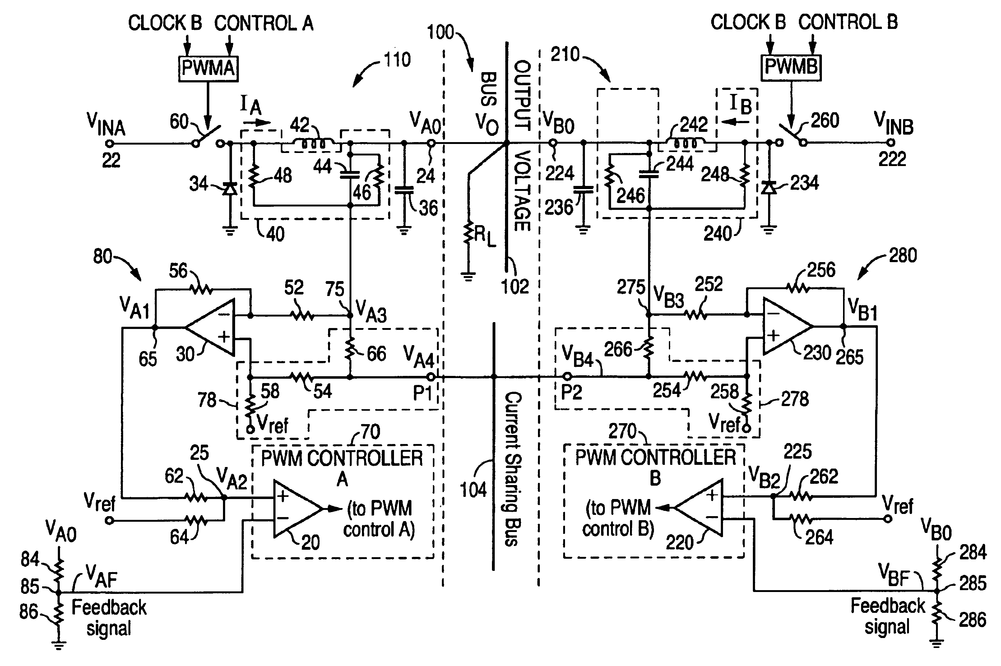
Figure 1 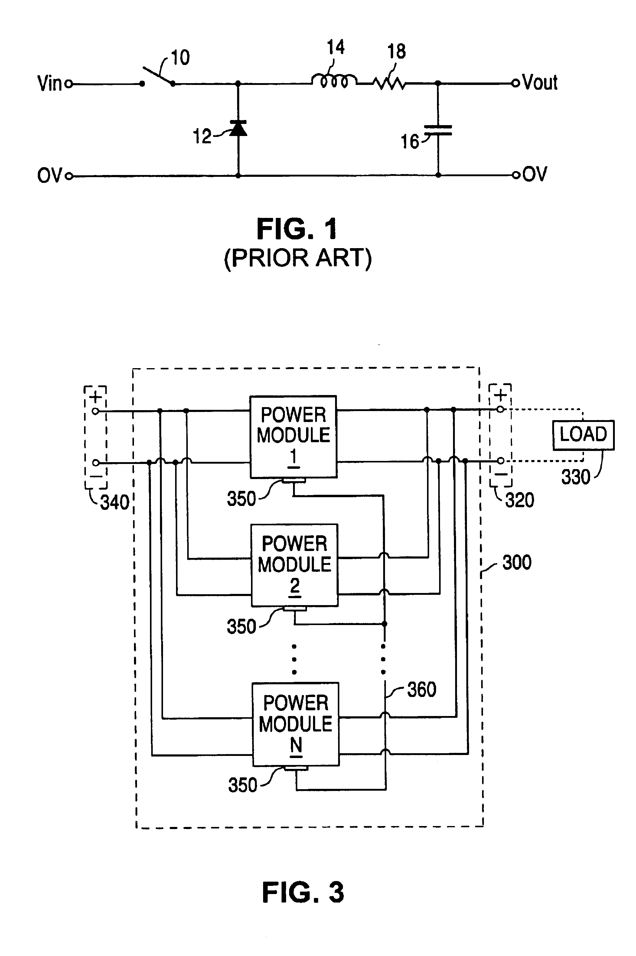
Figure 2 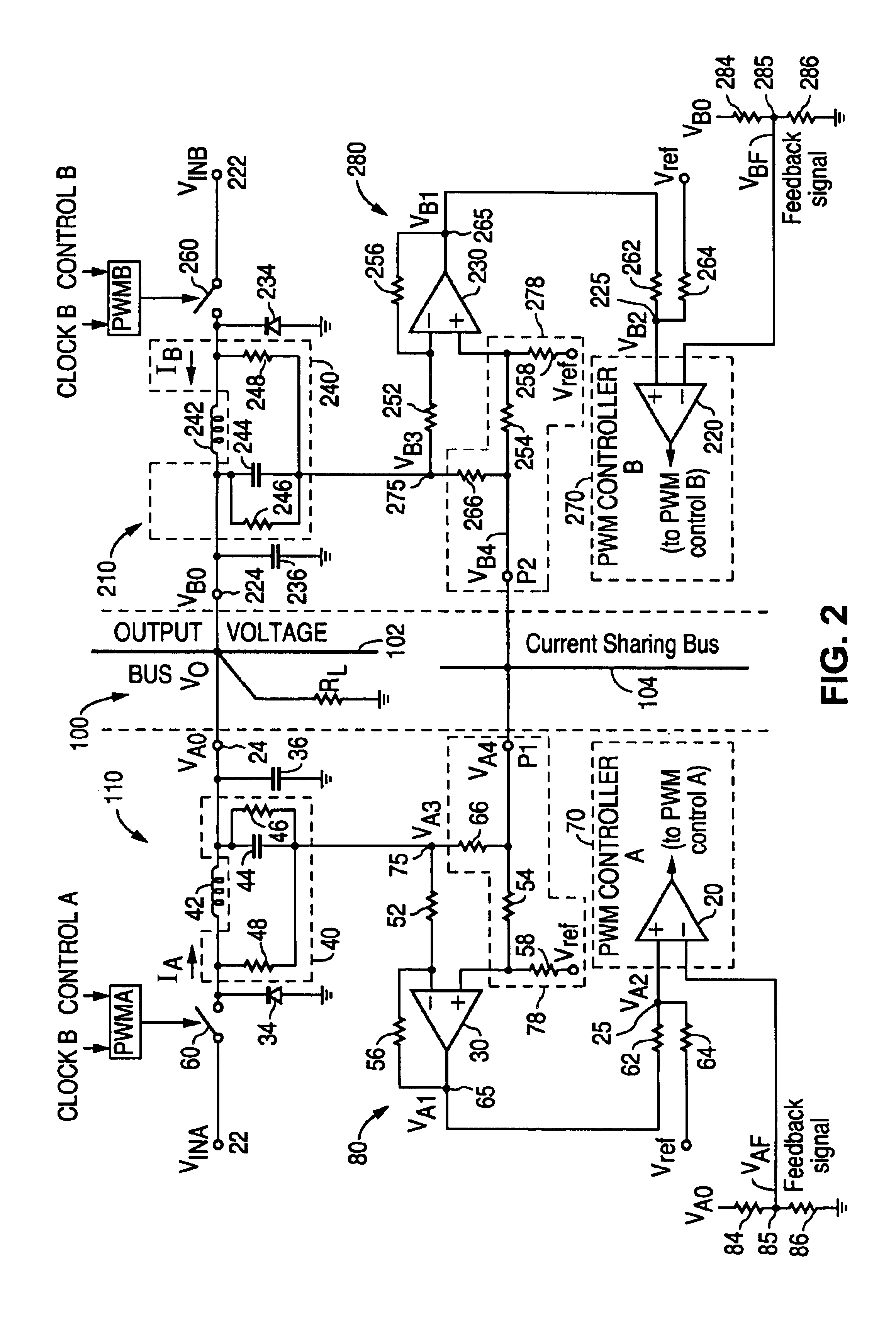
Figure 3
Abstract
Description
CROSS REFERENCE TO RELATED APPLICATIONS
[0001] This application is a continuation-in-part of application Ser. No. 10 / 377,864, entitled “Active Current Sharing Circuit”, filed Feb. 28, 2003 now abandoned.FIELD OF INVENTION
[0002] The present invention relates to power converters, and more particularly, to a circuit that efficiently provides active current sharing for paralleled power converters.BACKGROUND OF THE INVENTION
[0003] Many applications require that a higher level of current and power to be delivered to a load. At the same time, modem electronic devices require small, low cost, high density power converters. The paralleling of power converters provides a way for two or more individual, small, high density power converter modules to be coupled in parallel so as to supply the required power for high current loads and to provide redundancy. It is desirable that the individual converters in the parallel configuration share the load current equally in a stable, regulated manner. Furth...
Examples
Embodiment Construction
[0019]The present invention overcomes the drawbacks of known prior art circuits. A preferred embodiment of the active current sharing circuit for two paralleled DC Buck converters according to the present invention is shown in FIG. 2. The circuit 100 includes a power converter module 110 and a power converter module 210 connected in parallel. Converter modules 110 and 210 are preferably identical buck topology converters, shown as mirror images of each other in FIG. 2, having identical circuit components. As a result, the circuits and principles operating in one module also apply to the other module. Therefore, although some aspects of the converter module operation will be described solely with respect to converter module 110, the description applies to the other converter module 210. The corresponding elements in converter module 210 may also be given in parentheses herein for reference. For a preferred embodiment of FIG. 2, converter module 110 (210) has an input terminal 22 (222...