
Drill having construction for reducing thrust load in drilling operation, and method of manufacturing the drill
a drilling operation and construction technology, applied in the field of drilling, can solve the problems of undesirable reduction of rigidity or mechanical strength of the drill, difficult to reduce the thrust load applied, and inability to provide satisfactorily prolonged tool life, etc., to achieve the effect of reducing the thickness of the web, prolonging the tool life, and reducing the thirst load applied
Patent Information
- Authority / Receiving Office
- US · United States
- Patent Type
- Patents(United States)
- Current Assignee / Owner
- Publication Date
- 2005-08-02
- Estimated Expiration
- Not applicable · inactive patent
Smart Images
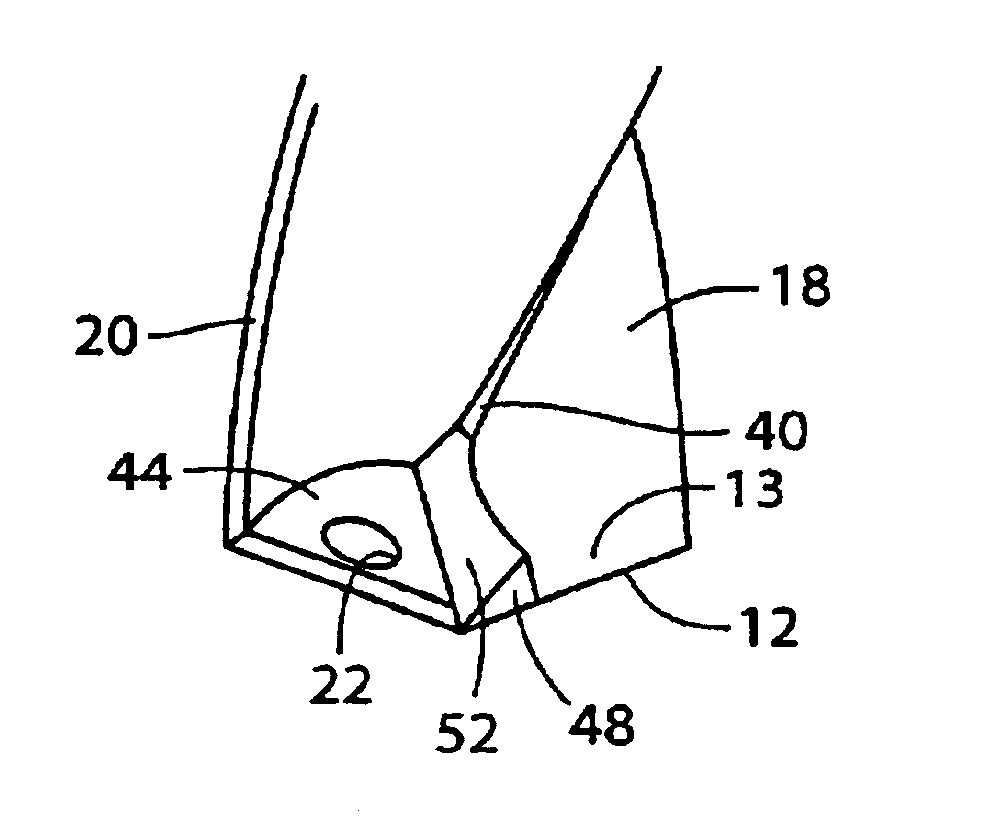
Figure 1 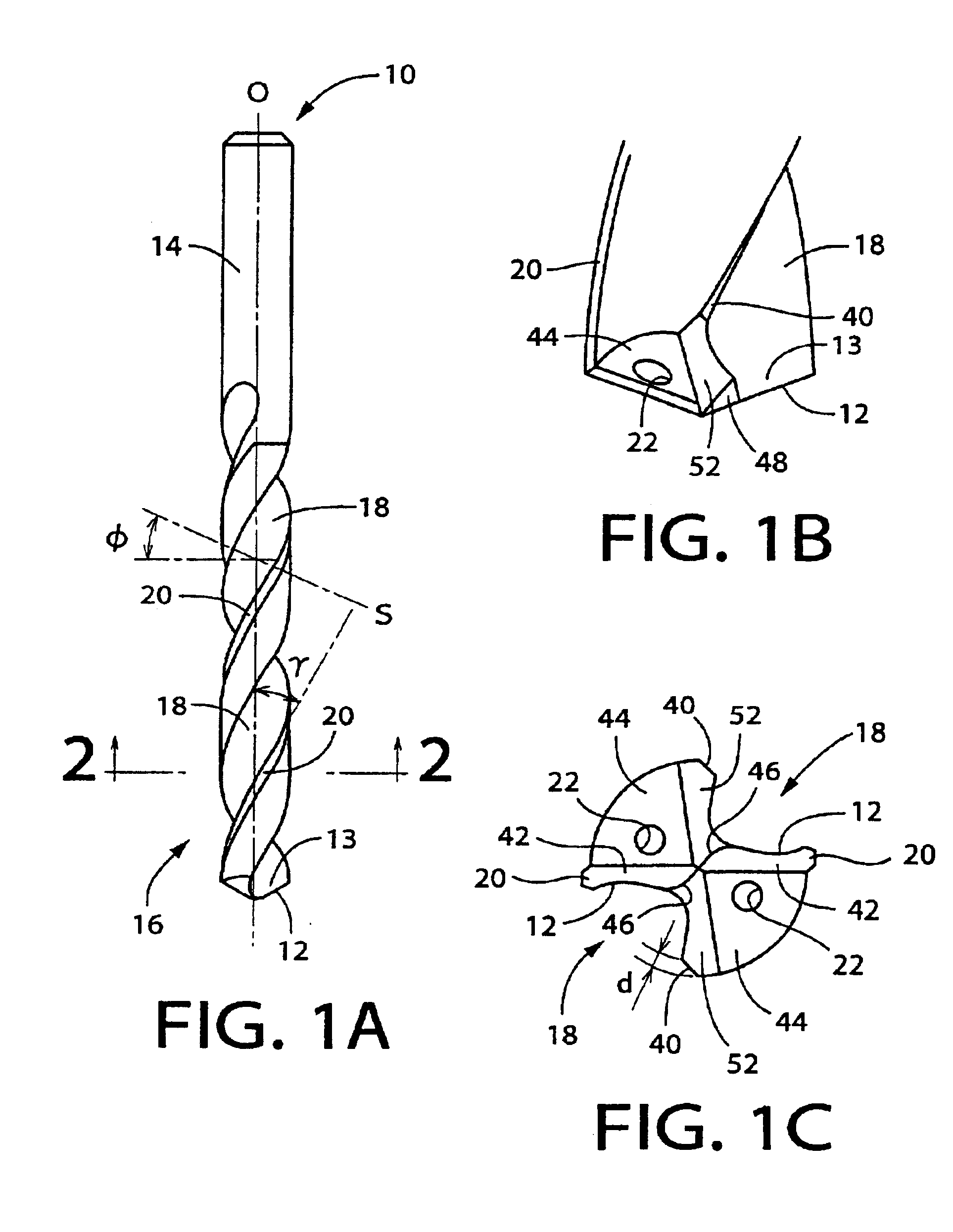
Figure 2 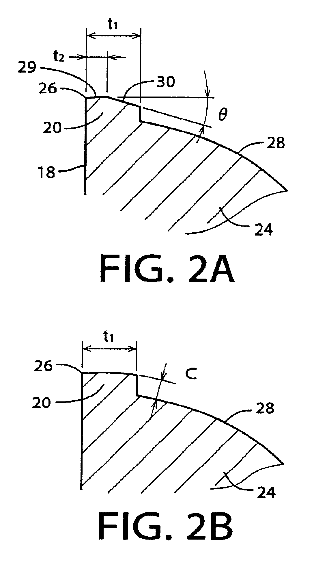
Figure 3
Abstract
Description
BACKGROUND OF THE INVENTION
[0001] 1. Field of the Invention
[0002] The present invention relates in general to a drill, and more particularly to techniques for providing a drill with a long tool life, by reducing a thrust load applied to the drill during a drilling operation for drilling a hole, and also by reducing a generation of friction heat, a wear of the drill and a cutting torque which are caused or increased by frictional contact of margins of the drill and an inner surface of the hole during the drilling operation.
[0003] 2. Discussion of the Related Art
[0004] There is widely known a drill which has cutting lips or edges formed in its axially distal end portion, and chip evacuation flutes formed to extend generally in its axial direction. The drill is used to originate or enlarge a hole in a workpiece, by rotating the drill about its axis and moving the drill and the workpiece relative to each other in the axial direction, so that the workpiece is cut with the cutting edges while...
Examples
Embodiment Construction
[0080]FIGS. 1A-1C show a drill 10 which is constructed according to an embodiment of this invention. FIG. 1A is a front elevational view of the drill 10 as seen in a direction perpendicular to an axis O of the drill 10. FIG. 1B is a front view showing in enlargement an axially distal end portion of the drill 10 in which a pair of cutting lips or edges 12 and their respective rake surfaces 13 are formed. FIG. 1C is a lower plan view of the drill 10, showing in enlargement the axially distal end portion of the drill 10. This drill 10 is of a two-fluted twist drill, and is formed of a cemented carbide. The drill 10 includes a cylindrical shank portion 14 and a cylindrical body portion 16 which are coaxial with each other and which are formed integrally with each other. The integrally formed cylindrical shank and body portions 14, 16 cooperate with each other to constitute a body of the drill 10, which is referred to as a drill body. The cylindrical body portion 16 has a pair of chip ev...