
Connection structure of induction line cover
a technology of induction line cover and connection structure, which is applied in the direction of power rails, power supply line details, transportation and packaging, etc., can solve the problems of physical contact between the joining member of the cover and the pickup coil, and the cover joining member is threatened with breaking, so as to achieve easy and reliable release
Patent Information
- Authority / Receiving Office
- US · United States
- Current Assignee / Owner
- Publication Date
- 2005-12-27
Smart Images
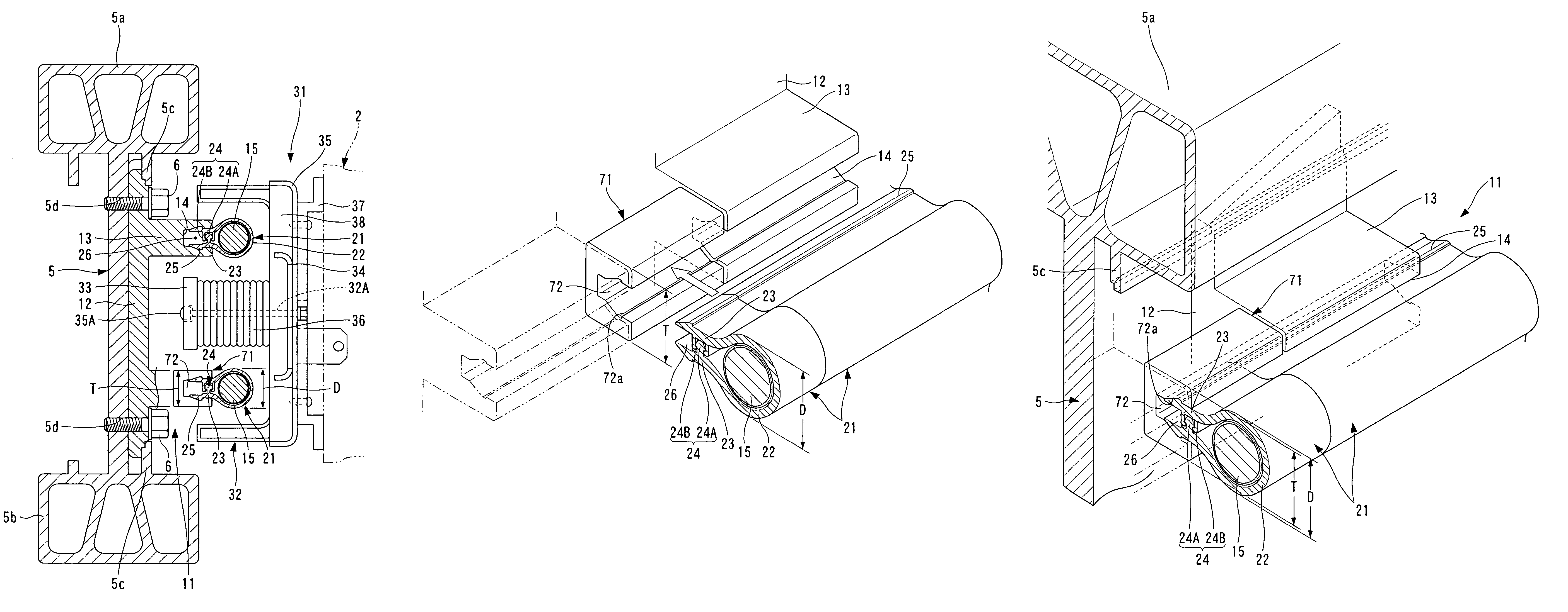
Figure 1 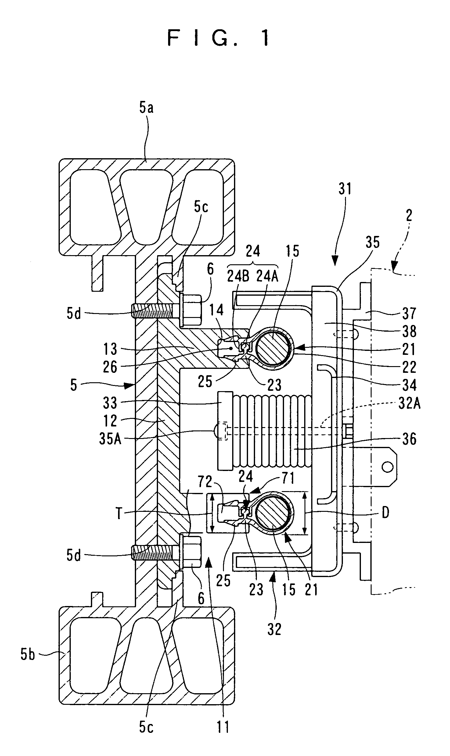
Figure 2 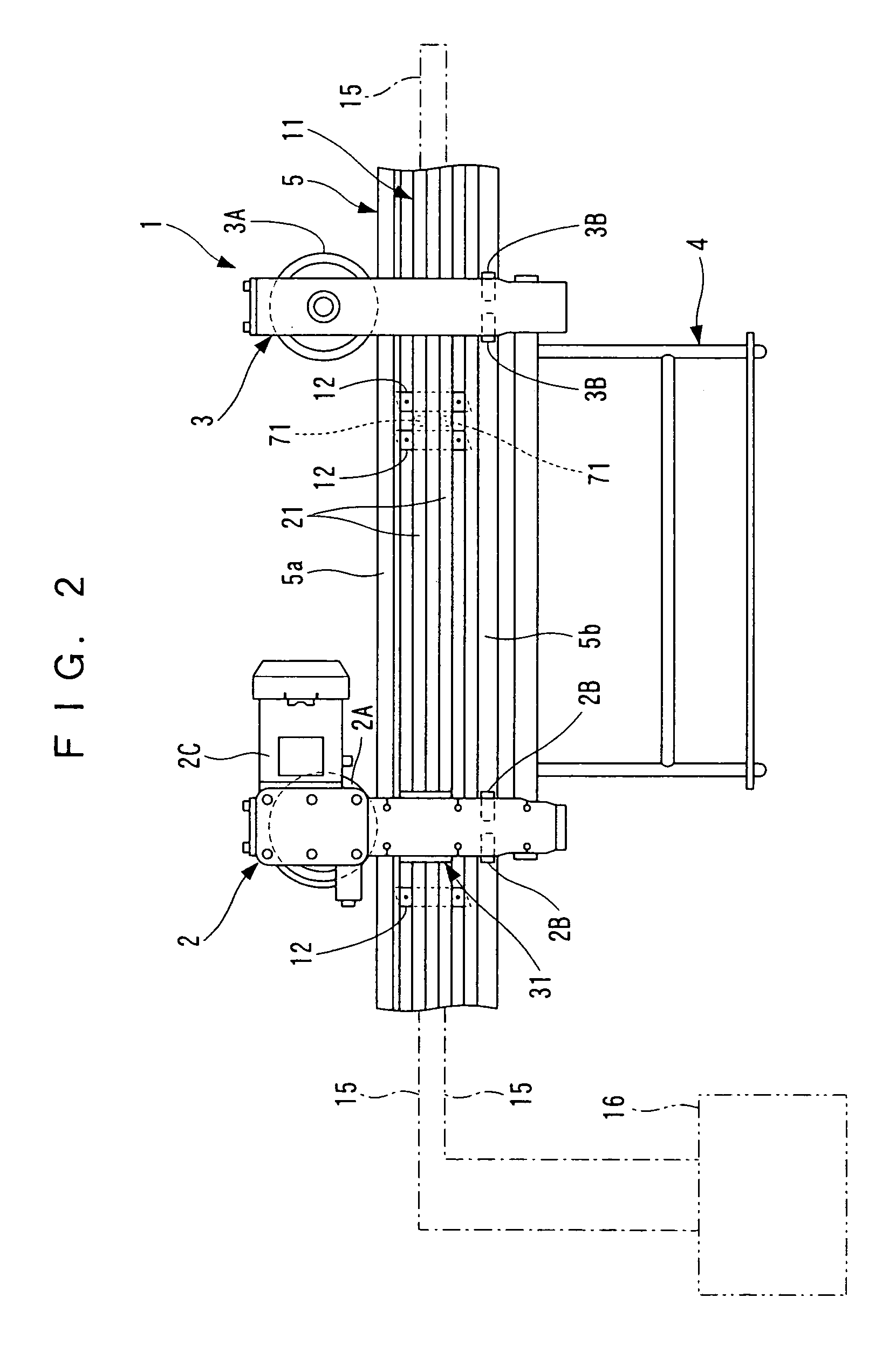
Figure 3
Abstract
Description
FIELD OF THE INVENTION
[0001] The present invention relates to a connection structure of an induction line cover used, for example, in a non-contact power supply system of a moving body.BACKGROUND OF THE INVENTION
[0002] Conventionally, when an induction line which passes a high-frequency sine-wave current is installed along a movement track of a moving body, and non-contact power supply system of a moving body in which a pickup coil for extracting power in a non-contact manner from the induction line is provided in the moving body, a feeder line holding device is used to hold the induction line.
[0003] As a conventional feeder line holding device of this type, for example, a configuration such as seen in Japanese Patent Laid-open No. 6-153305 has been proposed. That is, brackets are installed at prescribed intervals along the track on the guiding rail side of the moving body, and hangers are suspended from these brackets. A cover is provided for the induction line. This cover has a slit ...
Examples
first embodiment
[0028]Below, this invention, in which an induction line cover is adopted in a single-line induction line, is explained based on FIG. 1 through FIG. 10.
[0029]In FIG. 1 through FIG. 5, a transportation vehicle (one example of a moving body) 1 comprises a driving trolley 2, a driven trolley 3, and a freight transport carrier 4 supported by these trolleys 2 and 3; a guide rail (one example of a movement track) 5, which moveably guides the transportation vehicle 1, is provided.
[0030]The above driving trolley 2 comprises a traveling wheel 2A which meshes with the upper part of the guide rail 5, a steady roller 2B which makes contact from both lateral sides with the lower part of the guide rail 5, and a pickup unit 31; the traveling wheel 2A is driven by the electric motor with reduction gear 2C. The driven trolley 3 comprises a traveling wheel 3A which meshes with the upper part of the guide rail 5, and a steady roller 3B which makes contact from both lateral sides with the lower part of ...
second embodiment
[0060]Next, the invention is explained based on FIG. 11.
[0061]The cylinder-shaped section 22 of the induction line cover 21A has an inner-face shape capable of fitting a plurality of (two) induction lines 15 in a row.
third embodiment
[0062]Next, this invention is explained based on FIG. 12.
[0063]Because of the interference of the plate-shaped sections 23 having engaging / disengaging locks 24 and engaging sections 25 interfere, the induction line cover 21 cannot be used at curved sections of the guide rail 5. Hence in the curved sections, dedicated induction line covers 21B for use in curves are used. The covers 21B are formed with cut-outs 27 at prescribed intervals in the plate-shaped sections 23 of the induction line cover 21B, including the engaging / disengaging locks 24 and engaging sections 25, so as to be separated into a plurality of sections in the longitudinal direction. With these induction line covers 21B, the induction line 15 can be covered in close contact without difficulty even in curved sections of the guide rail 5.