
Friction clutch assembly
a clutch assembly and friction technology, applied in the field of friction clutches, can solve the problems of inertia of the cover plate becoming a hindrance to racing performance, inertia of the cover plate increasing undesirably, and the event of the cover plate failing, so as to reduce the deflection of the cover plate, improve reliability, and reduce the effect of inertia
Patent Information
- Authority / Receiving Office
- US · United States
- Patent Type
- Patents(United States)
- Current Assignee / Owner
- Publication Date
- 2007-04-17
- Estimated Expiration
- Not applicable · inactive patent
Smart Images
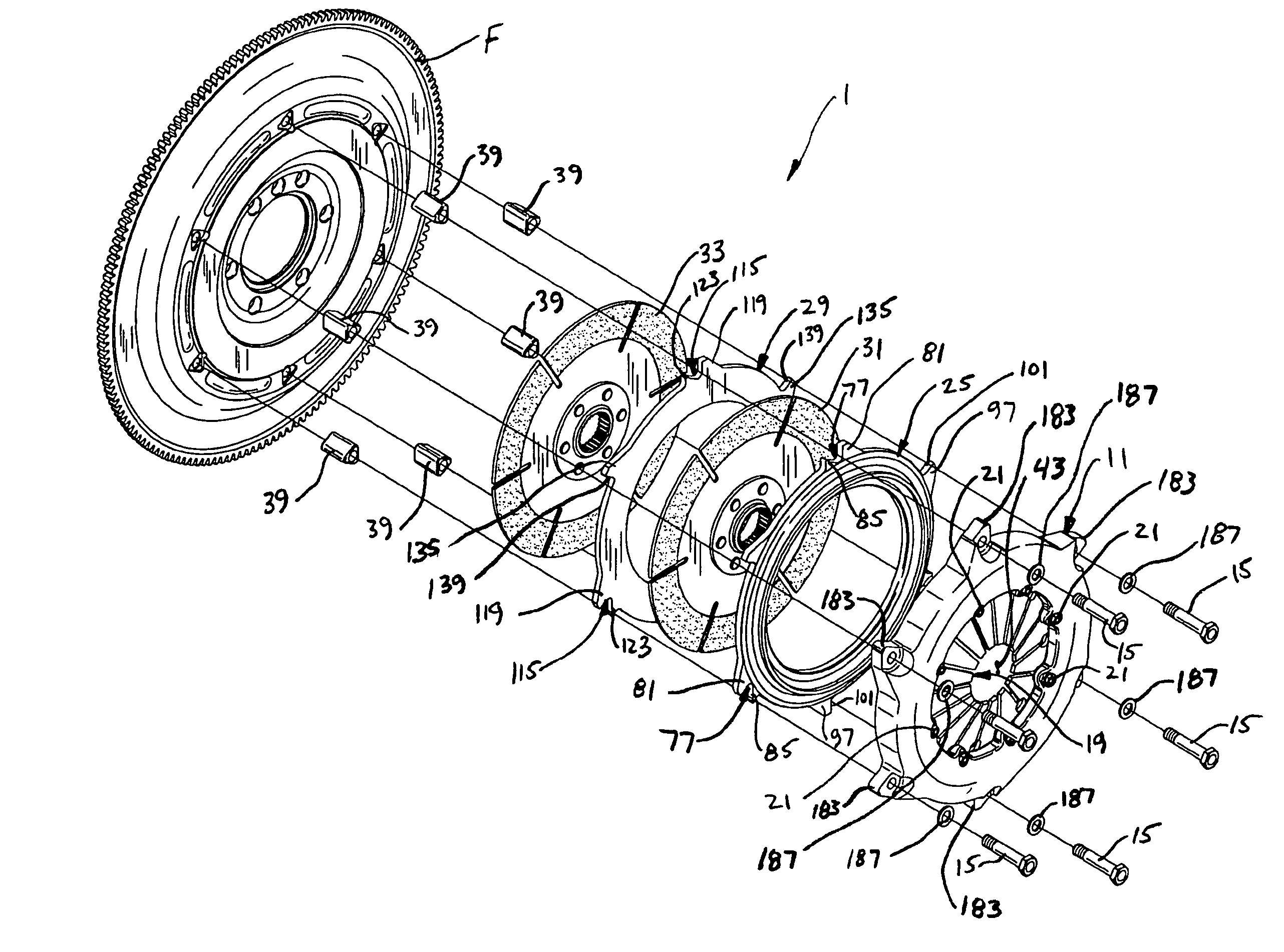
Figure 1 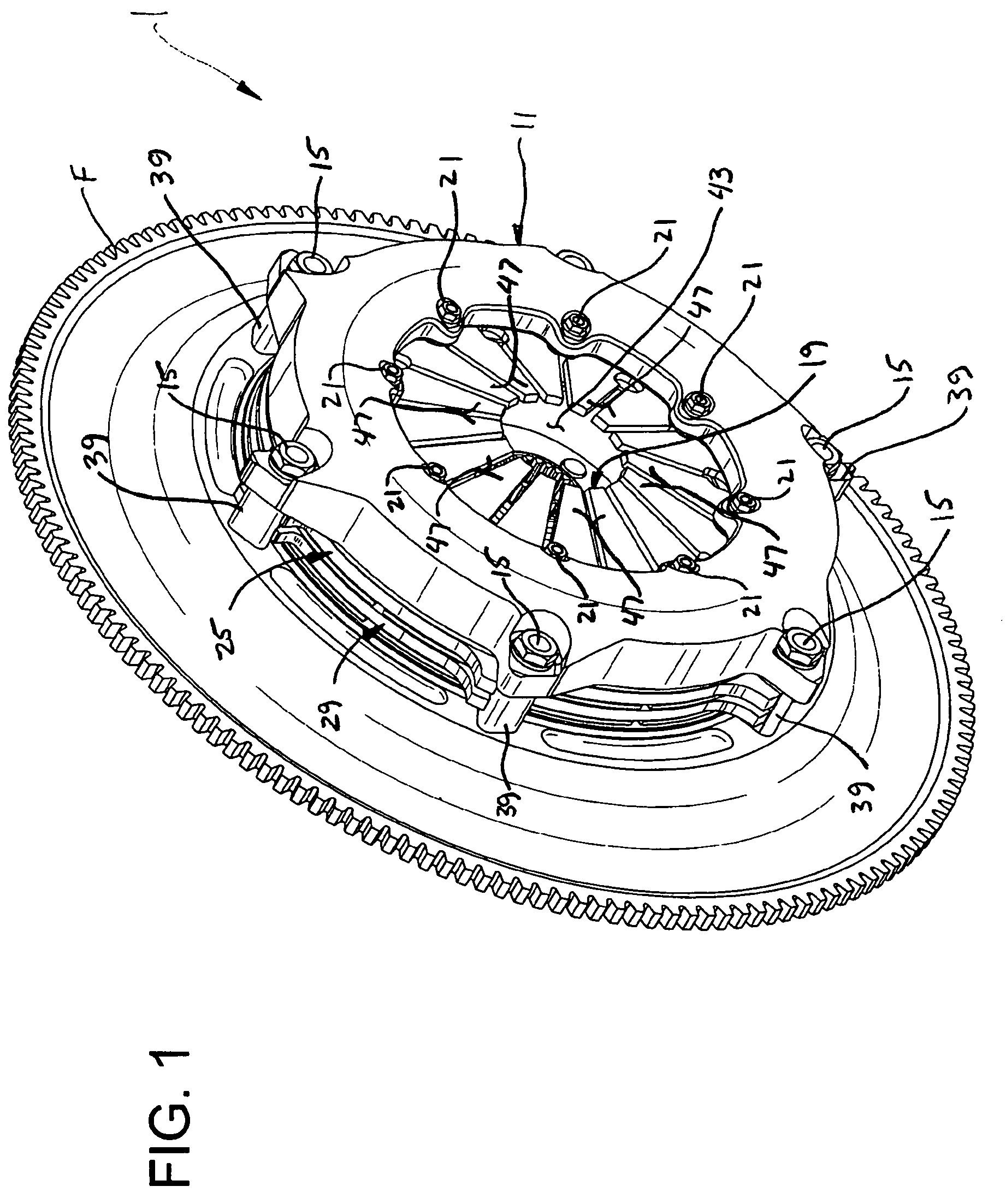
Figure 2 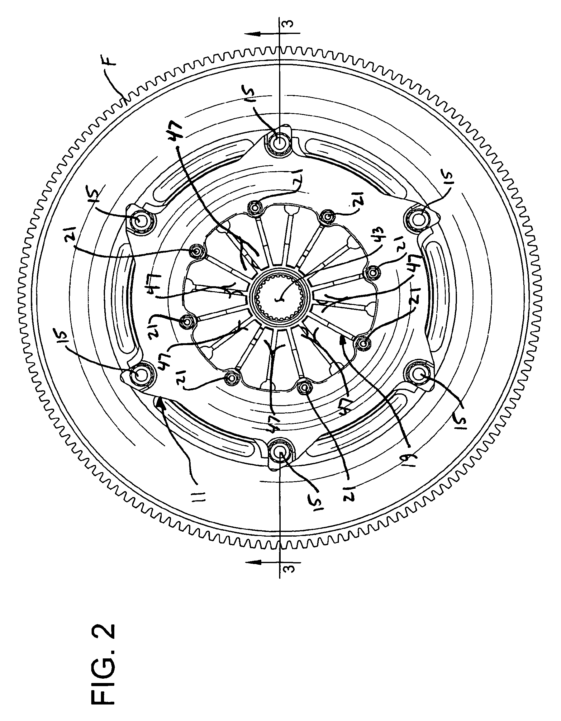
Figure 3
Abstract
Description
CROSS-REFERENCE TO RELATED APPLICATION
[0001] This application is a divisional of U.S. patent application Ser. No. 10 / 727,687, filed Dec. 4, 2003, now abandoned, the entire disclosure of which is incorporated herein by reference.BACKGROUND OF THE INVENTION
[0002] The present invention relates generally to friction clutches, and in particular to a clutch assembly used in high performance vehicles such as racing cars.
[0003] As is well known, vehicle clutches operate to selectively couple and decouple an engine to a drive shaft for the purpose of starting the engine while the vehicle is in gear, bringing the vehicle to a stop while the engine is running, changing gears while the vehicle is in motion and putting the vehicle in motion from a dead stop. Conventional clutches include a cover assembly having an annular cover plate and at least one annular pressure plate connected to the cover plate for conjoint rotation with the cover plate. The cover plate is fixedly attached to a flywheel driv...
Examples
Embodiment Construction
[0032]Referring now to the drawings, and first to FIGS. 1–3, a friction clutch assembly of the present invention is generally indicated at 1. The friction clutch assembly interconnects a powered, driving shaft A to a driven shaft B. Typically the driving shaft A is an engine crankshaft of an automotive vehicle which is attached to a flywheel F, and the driven shaft is a transmission gearbox input shaft. The driving shaft A and driven shaft B are axially aligned and can be operatively connected through the clutch 1 so that torque is transmitted and the shafts rotate together. A driver of the vehicle uses the clutch 1 to selectively disconnect the shafts A, B, interrupting the transmission of torque, in order to permit a gear shifting operation in the transmission.
[0033]As seen in FIGS. 3 and 4, the friction clutch assembly 1 includes a cover, generally indicated 11, attached to the flywheel F by conventional fasteners 15 for fixed rotational engagement with the driving shaft A. In th...