
Electric/magnetic field sensor
a magnetic field and sensor technology, applied in the direction of resistance/reactance/impedence, electrostatic field measurement, instruments, etc., can solve the problems of limited sensitivity at low frequencies, poor response, and difficulty in fabricating a sensor having a wide pass band, so as to increase the useful wide bandwidth and expand the useful wide bandwidth
Patent Information
- Authority / Receiving Office
- US · United States
- Patent Type
- Patents(United States)
- Current Assignee / Owner
- Publication Date
- 2009-01-27
- Estimated Expiration
- Not applicable · inactive patent
Smart Images
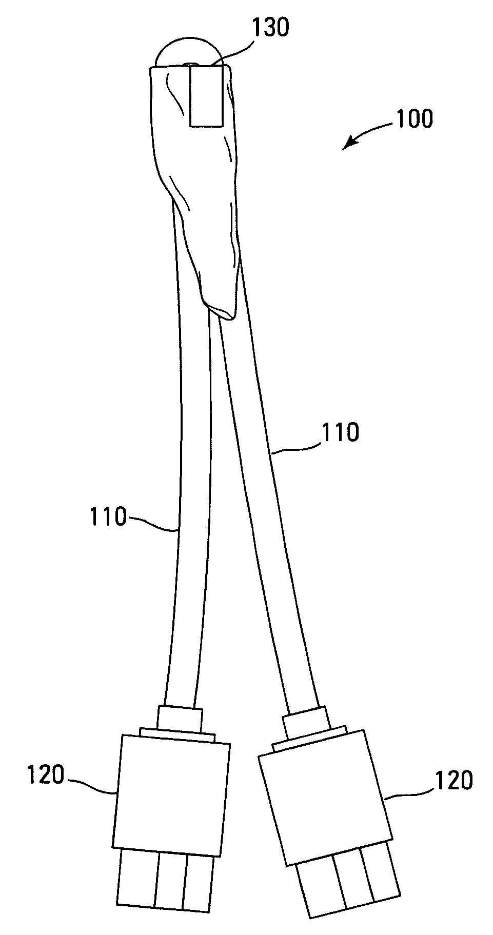
Figure 1 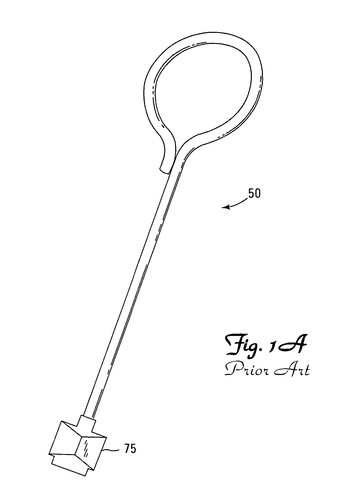
Figure 2 
Figure 3
Abstract
Description
RELATED APPLICATION DATA
[0001] This application claims priority from U.S. Provisional Application No. 60 / 605,069, filed Aug. 27, 2004STATEMENT REGARDING FEDERALLY SPONSORED RESEARCH OR DEVELOPMENT
[0002] The U.S. Government has a paid-up license in this invention and may have the right in limited circumstances to require the patent owner to license others on reasonable terms as provided for by the terms of DE-FG02-00ER45831 awarded by the Department of Energy.BACKGROUND OF THE INVENTION
[0003] 1. Field of the Invention
[0004] The embodiments of the present invention relate to sensors for measuring magnetic field and electric field phenomena at the same time at the same point in space.
[0005] 2. Background of the Art
[0006] Conventional small magnetic field sensors (commonly referred to as B-dots) consist of a coaxial cable with a coil located at the cable end. The center wire of the coaxial cable extends beyond the outer shield and is shaped in the form of a coil. Typically, the coil may be a ...
Examples
Embodiment Construction
[0022]A conventional differential B-dot makes use of two nearly identical coils spaced closely together in a nearly unique orientation. For packaging purposes, the differential B-dot is housed within a conductive block filled with a dielectric substance. This packaging is not necessary in the differential B-dot design except when trying to eliminate or control proximity effects. Interconnection is accomplished using two pieces of transmission line one for each dot in the differential B-dot set. However, under close scrutiny, the standard and differential B-dot reveals critical limitations. The standard B-Dot suffers from symmetry and ground loop issues. For the differential B-dot to exhibit a spurious noiseless signal, one requires (this assumes that the coil end is terminated on the grounding shield): 1. Identical probes, 2. Identical relative ground line geometry that includes line lengths, bends and twists in the line, line cross-sectional dimensions, line orientations, 3. Line a...