
Canister heater
Patent Information
- Authority / Receiving Office
- US · United States
- Current Assignee / Owner
- Publication Date
- 2009-04-07
- Estimated Expiration
- Not applicable · inactive patent
Smart Images
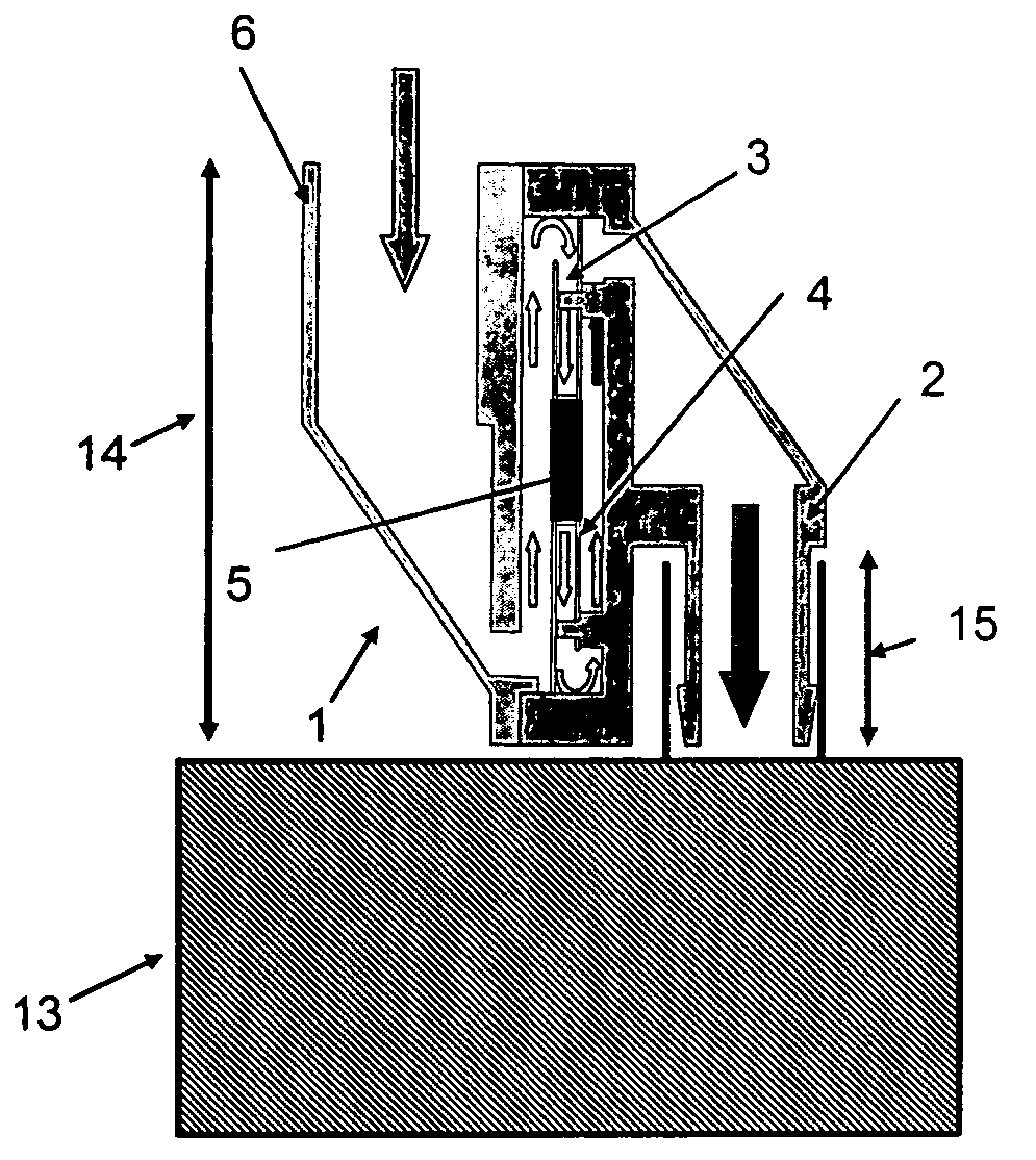
Figure 1 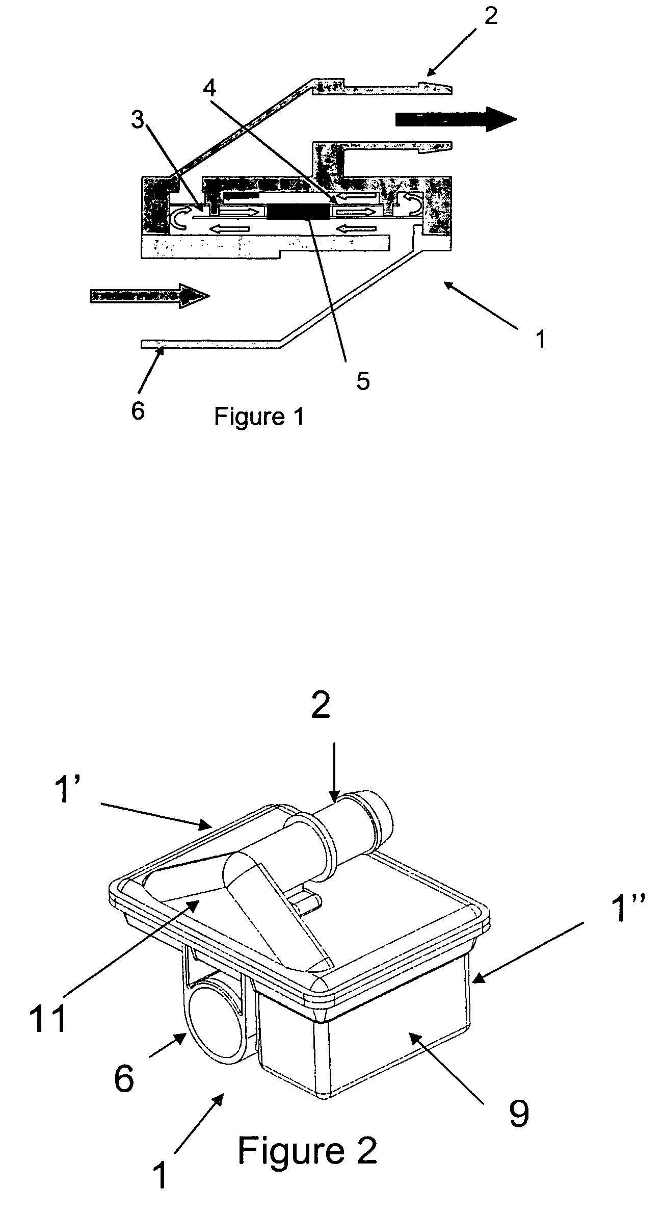
Figure 2 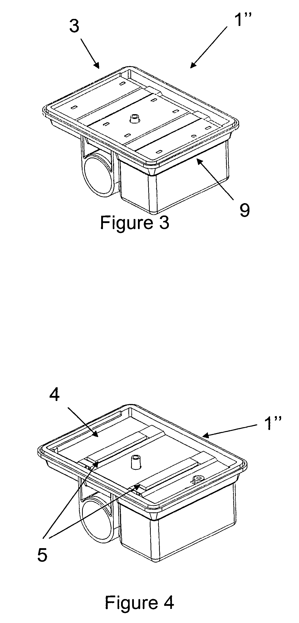
Figure 3
Abstract
Description
BACKGROUND OF THE INVENTION
[0001] 1. Field of the Invention
[0002] The present invention relates to a heater for heating a fluid intended to pass through a fuel tank canister.
[0003] 2. Description of the Related Art
[0004] Fuel vapours escaping from a fuel system are a source of hydrocarbon emissions in motor vehicles. Fuel leaks due to lack of sealing and also losses by evaporation are most particularly the subject of increasingly stringent regulations, especially for applications in motor vehicles.
[0005] Now, fuel tanks, in particular for motor vehicles, usually have a venting orifice for balancing the internal pressure with the atmospheric pressure, for example during variations in the fuel level resulting from filling the tank or from the consumption of fuel by the engine, or else during variations in temperature. Therefore, to meet the aforementioned standards, this venting orifice is conventionally connected to atmosphere via a duct and a chamber, usually called a canister, which con...
Examples
Embodiment Construction
[0057]Referring now to the drawings, wherein like reference numerals designate identical or corresponding parts throughout the several views.
[0058]FIG. 1 illustrates schematically a heater comprising a casing (1) provided with two couplers (2) and (6), the coupler (2) of which is intended to be connected to the venting outlet of a canister and the coupler (6) is intended to be connected to an OBD device. The purge air flows through the heater, between the plates (3) and (4), in the direction of flow indicated by the arrows. A heating element (5) is inserted between the plates (3) and (4).
[0059]FIGS. 2 to 6 show various views of one possible embodiment of the heater according to the invention.
[0060]The casing (1) in FIG. 2 comprises two parts (1′) and (1″) that are provided with respective couplers (2) and (6). Furthermore, the part (1″) of the casing (1) includes a housing (9) for an electronic controller (not shown).
[0061]In FIG. 3, the part (1′) has been omitted so as to show only...