
Low-profile optical mounting assembly
a technology of optical mounting and low-profile, which is applied in the field of low-profile optical mounting assemblies, can solve the problems of eye strain, discomfort and even headaches, and the physical bulk of existing designs, and achieve the effects of enhancing peripheral vision, reducing visual obscuration, and low-profile design
Patent Information
- Authority / Receiving Office
- US · United States
- Patent Type
- Patents(United States)
- Current Assignee / Owner
- Publication Date
- 2010-09-07
Smart Images
Figure 1 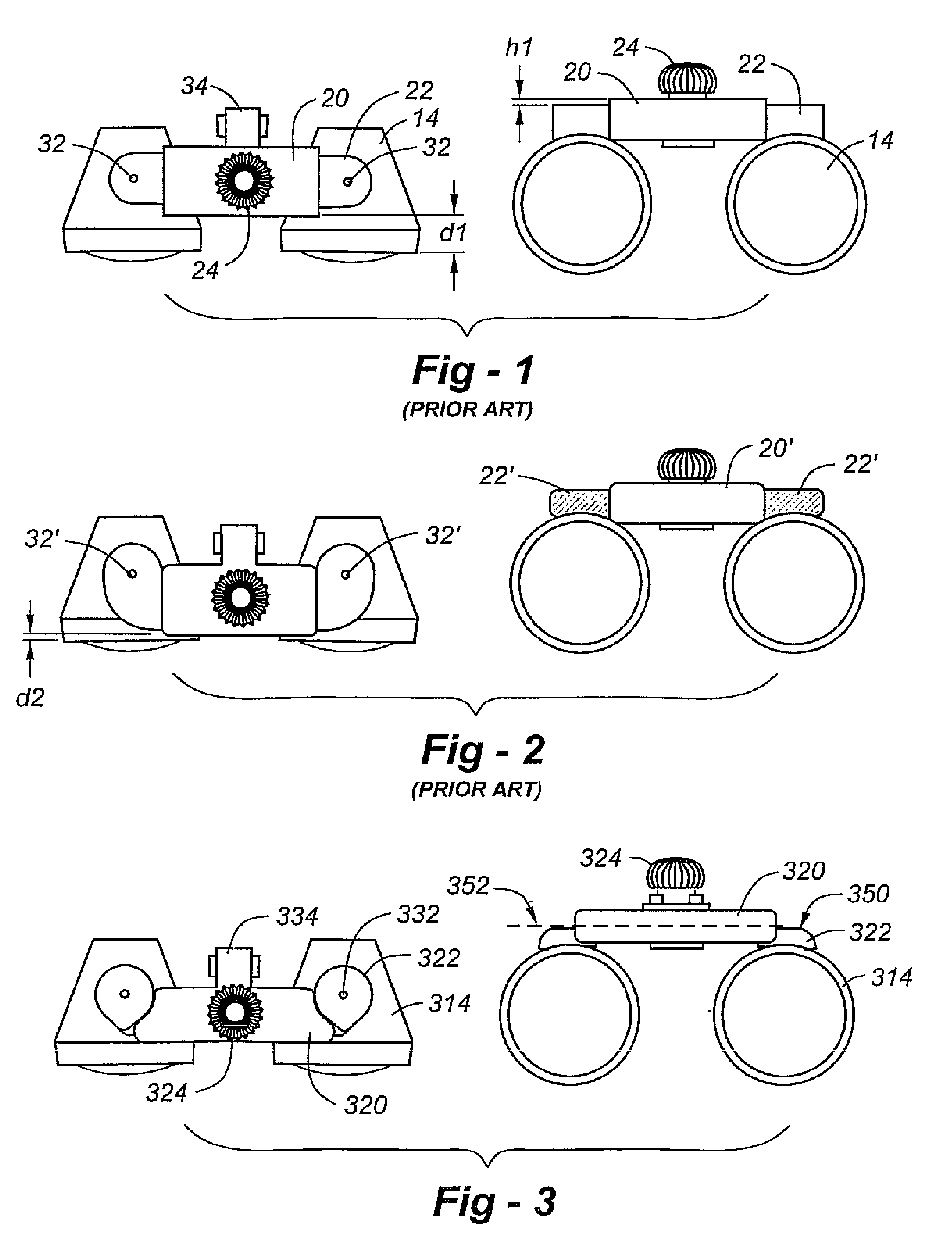
Figure 2 
Figure 3
Abstract
Description
FIELD OF THE INVENTION
[0001] This invention relates generally to ocular mounting assemblies of the type used in surgical, medical and dental applications and, in particular, to a stable, low-profile assembly affording enhanced peripheral vision.BACKGROUND OF THE INVENTION
[0002] Telescopic instruments are widely used for magnifying a work area during precision work such as delicate surgery, dental work, inspection of circuit board solder joints, and assembly of miniature parts. A typical telemicroscopic instrument includes a pair of telemicroscopic loupes which are adjustably mounted to an eyeglass frame or headband. The telescopic loupes combine the long working distance of the telescope with the high quality magnification of the microscope. This type of optical instrument provides the user, a surgeon, for example, with a magnified image of the work area with a field of view at about an arm's length.
[0003] As one example, the ocular mounting assembly disclosed in U.S. Pat. No. 5,381,26...
Examples
Embodiment Construction
[0013]Having discussed FIGS. 1 and 2, the reader's attention is directed to FIG. 3, which shows an ocular mounting assembly constructed in accordance with the invention. The housing is shown at 320, including an outwardly extending portion 334 having side pins that engage with a hinged pivot assembly (not shown), which may be similar to, if not identical to, prior-art hinge assemblies facilitating an eyeglass or head-band mount. The adjustment knob is shown at 324, and the oculars are shown at 314.
[0014]Importantly, according to the invention, the top surface 350 of each support arm 322 has material removed, allowing the top of the support arm to be at or below the horizontal centerline 352 of the housing 320. This removed material decreases visual obscuration and enhances peripheral vision for the user. In the preferred embodiment, the dimension between the top of the arms major length to the area directly above the ocular is 0.099″+ / −0.010″ (2.51+ / −0.25 mm). The dimension from the...