
Multilayer capacitor
a multi-layer capacitor and capacitor technology, applied in the direction of capacitors, fixed capacitor details, fixed capacitors, etc., can solve the problems of difficult to achieve further reduction in esl, limit of esl reduction in terms of structure, etc., to prevent thermal shock damage, reduce esl, and reduce suction failure
Patent Information
- Authority / Receiving Office
- US · United States
- Patent Type
- Patents(United States)
- Current Assignee / Owner
- Publication Date
- 2012-01-31
Smart Images
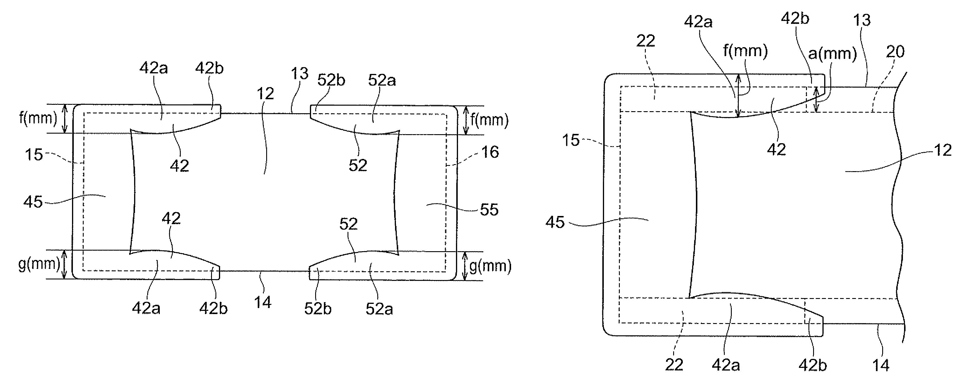
Figure 1 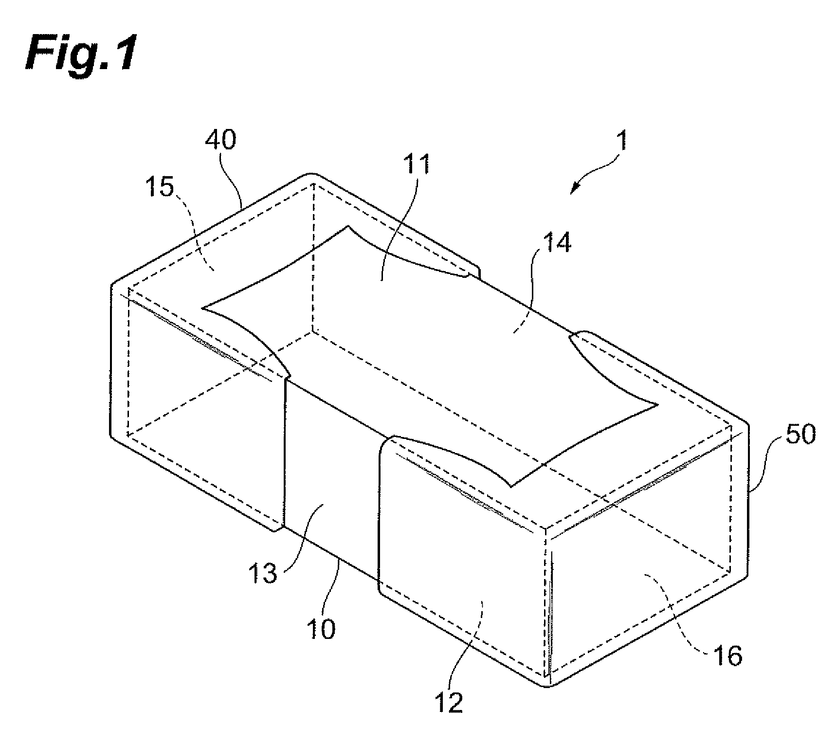
Figure 2 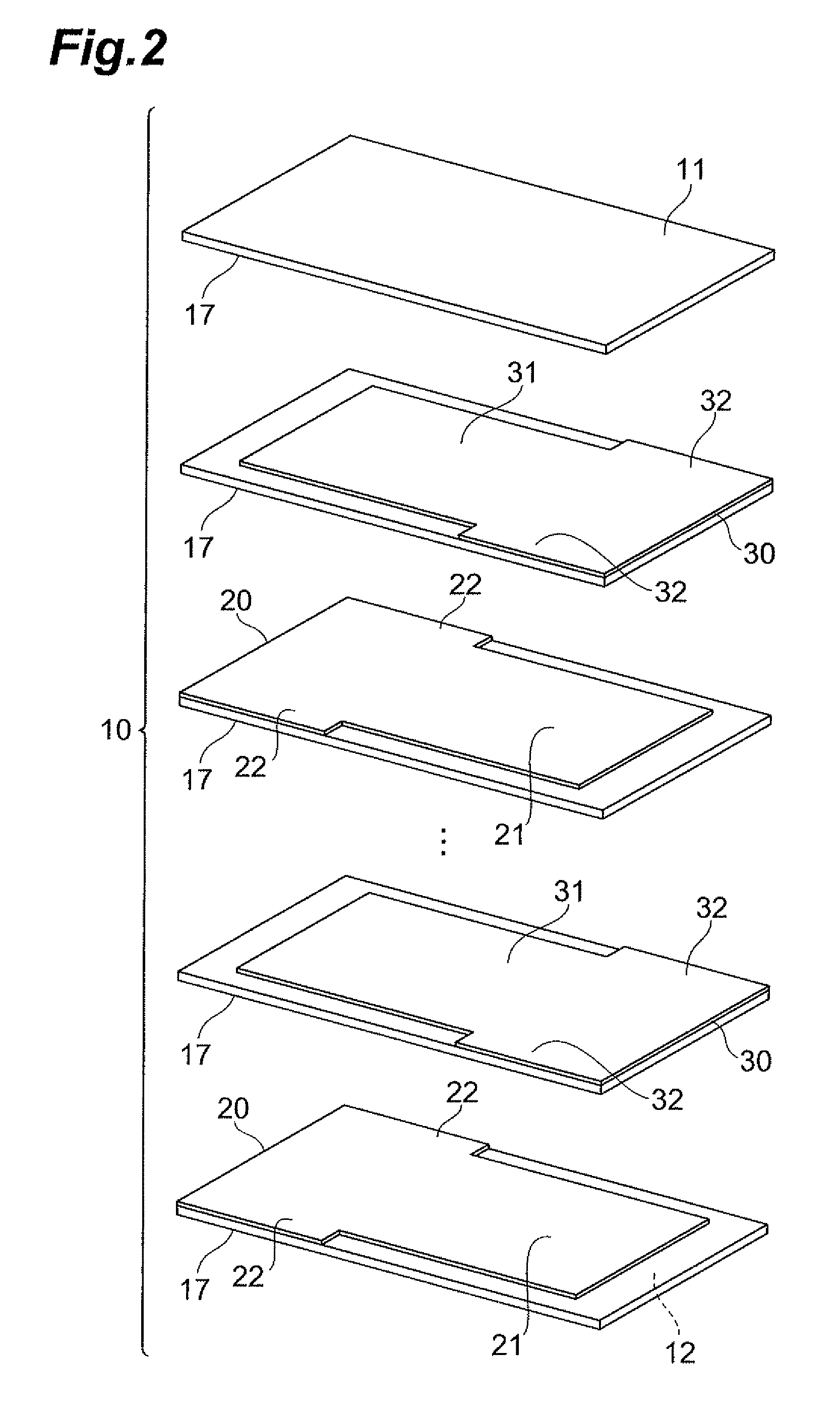
Figure 3
Abstract
Description
BACKGROUND OF THE INVENTION
[0001] 1. Field of the Invention
[0002] The present invention relates to a multilayer capacitor.
[0003] 2. Related Background Art
[0004] There is a known multilayer capacitor having a dielectric element body of a nearly rectangular parallelepiped shape in which a plurality of dielectric layers are laminated together, two types of internal electrodes arranged in the dielectric element body, and two terminal electrodes each extending over three side faces of the dielectric element body (e.g., cf. Japanese Patent Application Laid-open No. 2003-051423). In the multilayer capacitor disclosed in this patent document, each of the two types of internal electrodes has a structure in which it is drawn out to the two side faces of the dielectric element body, and thus electric currents flow in opposite directions in the two types of internal electrodes, whereby magnetic fields made thereby cancel each other to reduce the equivalent series inductance (which will be referred ...
Examples
Embodiment Construction
[0032]The preferred embodiments will be described below in detail with reference to the accompanying drawings. In the description the same elements or elements with the same functionality will be denoted by the same reference symbols, without redundant description. A configuration of a multilayer capacitor 1 according to an embodiment of the present invention will be described with reference to FIGS. 1 to 9.
[0033]The multilayer capacitor 1, as shown in FIGS. 1 and 2, has a capacitor element body 10, first internal electrodes 20, second internal electrodes 30, a first terminal electrode 40, and a second terminal electrode 50.
[0034]The capacitor element body 10 is of a nearly rectangular parallelepiped shape and has first and second principal faces 11, 12 of a rectangular shape opposed to each other, first and second side faces 13, 14 opposed to each other and extending in the long-side direction of the first and second principal faces 11, 12 so as to connect the first and second prin...