
Spacer nut manufacturing method
a manufacturing method and spacer technology, applied in the direction of threaded fasteners, bolts, other domestic articles, etc., can solve the problems of large introduction cost, inability to form a roll shape, and generally rather expensive nc lathes, so as to reduce the number of times that the material is replenished, reduce the cost of material supply, and high production efficiency
Patent Information
- Authority / Receiving Office
- US · United States
- Patent Type
- Patents(United States)
- Current Assignee / Owner
- Publication Date
- 2012-09-11
- Estimated Expiration
- Not applicable · inactive patent
Smart Images
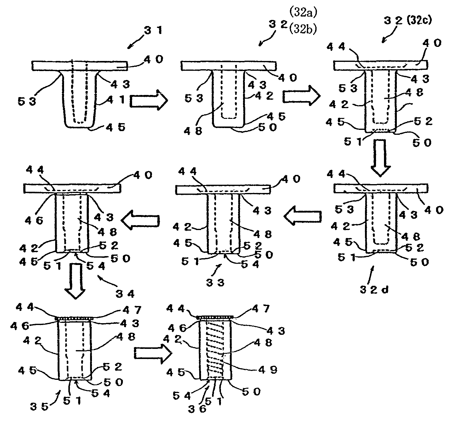
Figure 1 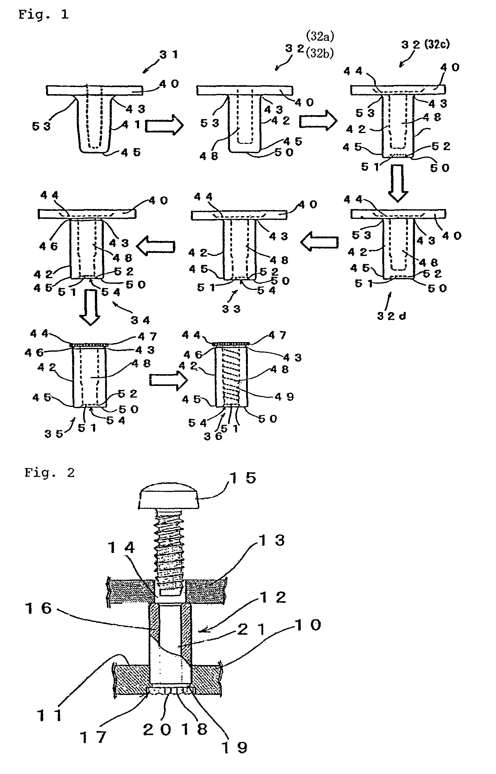
Figure 2 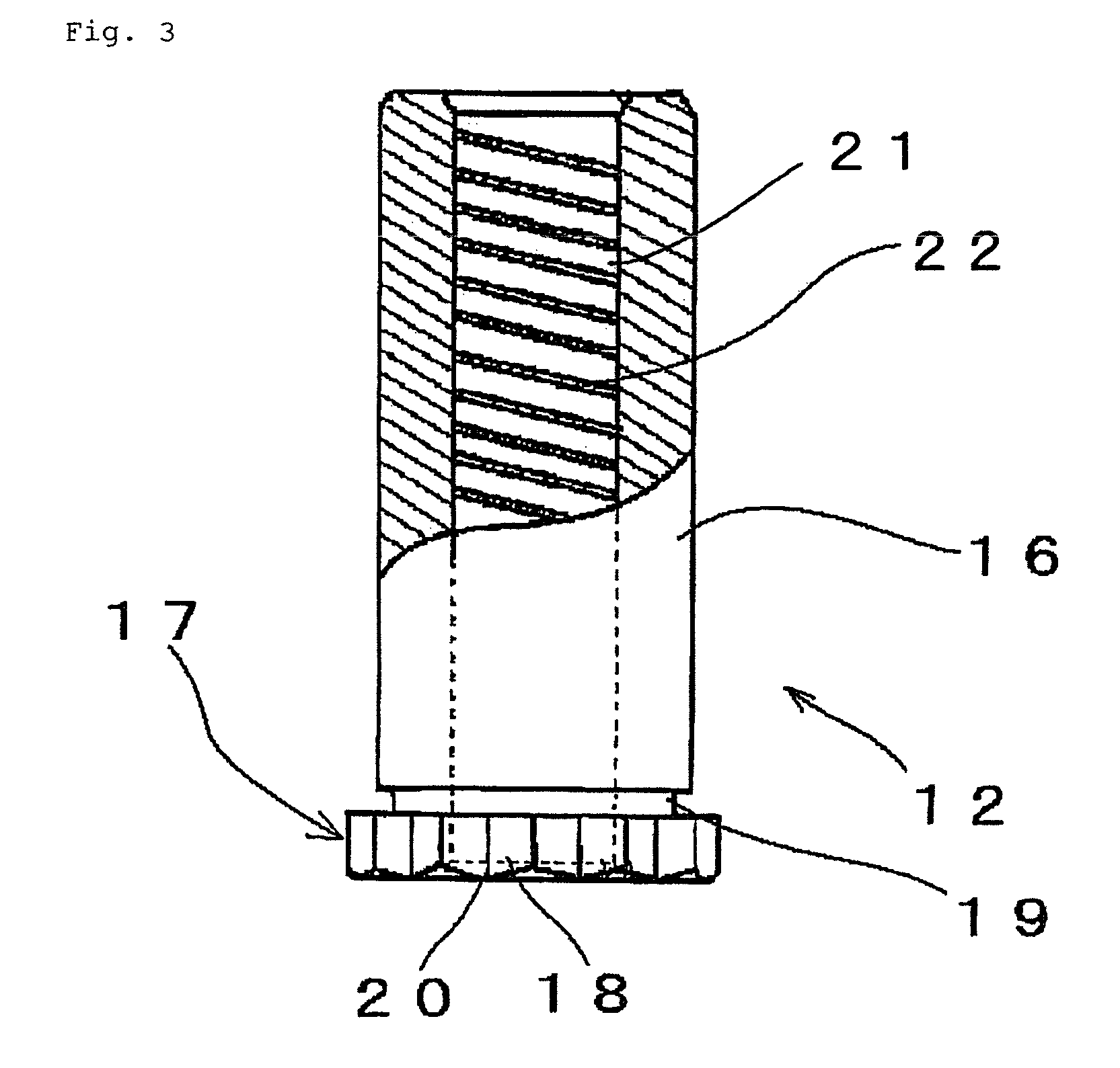
Figure 3
Abstract
Description
TECHNICAL FIELD
[0001] The present invention relates to a method of manufacturing a spacer nut which is arranged between a casing and a board of a computer or the like in order to fix the casing and the board in position while keeping them spaced apart from each other by a predetermined distance dimension when mounting the board in the casing.BACKGROUND ART
[0002] When fixing a board in position within the casing of a personal computer or the like, it is necessary for the board to be spaced apart from the inner side surface of the casing by a predetermined dimension in order to prevent confinement of heat, a shock from the outside, etc. Thus, as shown in FIG. 2, a spacer nut 12 formed in a substantially cylindrical configuration is forced into an inner side surface 11 of a casing 10 and fixed in position so as to be erect, and a screw passing hole portion 14 previously provided in a board 13 and the spacer nut 12 are matched with each other; then, the board 13 is placed on the spacer nu...
Examples
Embodiment Construction
[0074]A mode for carrying out the present invention will be described with reference to the drawings.
[0075]As shown in FIG. 1, a spacer nut manufacturing method 30 according to the present invention comprises: a first step 31 of forming a protrusion 41 of a predetermined length by press working on a metal plate material 40 having a predetermined thickness dimension; a second step 32 of forging the protrusion 41 into a shaft portion 42 in the form of a bottomed cylinder and forming a flange portion 44 at the peripheral edge of a proximal end portion 43 of the shaft portion 42 by press working; a third step 33 of forming an opening 54 at a distal end portion 45 of the shaft portion 42 by press working; a fourth step 34 of pressing the proximal end portion 43 of the shaft portion 42 radially inwards to form a groove portion 46 extending in the circumferential direction of the shaft portion 42 by press working; a fifth step 35 of stamping the flange portion 44 from the metal plate mater...