
Lamp with wide-angle light emission and bulb thereof
a technology of light emission and wide-angle lamps, which is applied in the direction of planar light sources, semiconductor devices of light sources, lighting and heating apparatus, etc., can solve the problems of limited angle illumination range of this conventional lamp b>8/b>, and the inability to enhance, etc., to achieve the effect of emitted light over a wide angle, and the limitation of the illumination range of the conventional lamp b>8/b>
Patent Information
- Authority / Receiving Office
- US · United States
- Patent Type
- Patents(United States)
- Current Assignee / Owner
- Publication Date
- 2014-04-15
- Estimated Expiration
- Not applicable · inactive patent
Smart Images
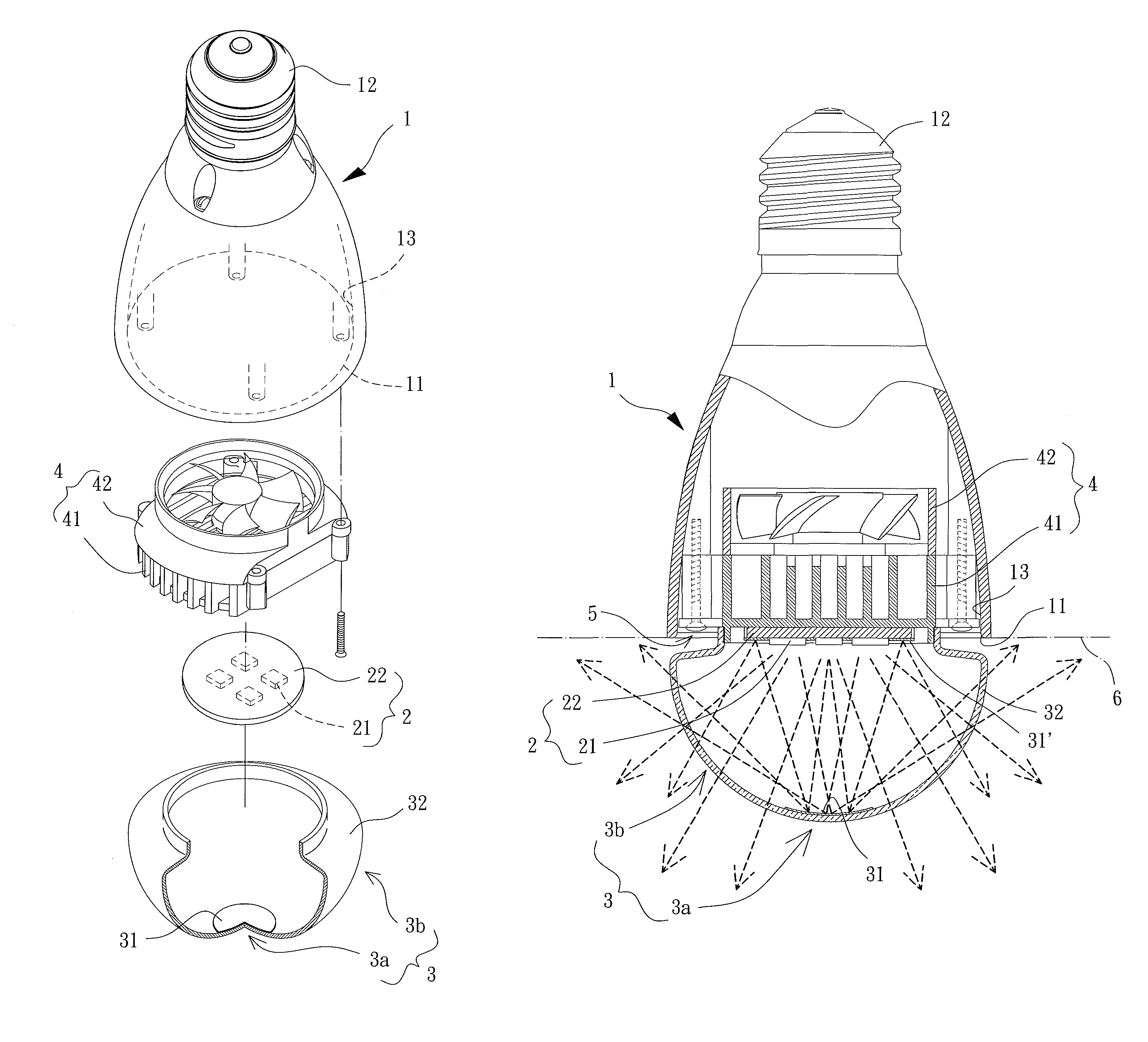
Figure 1 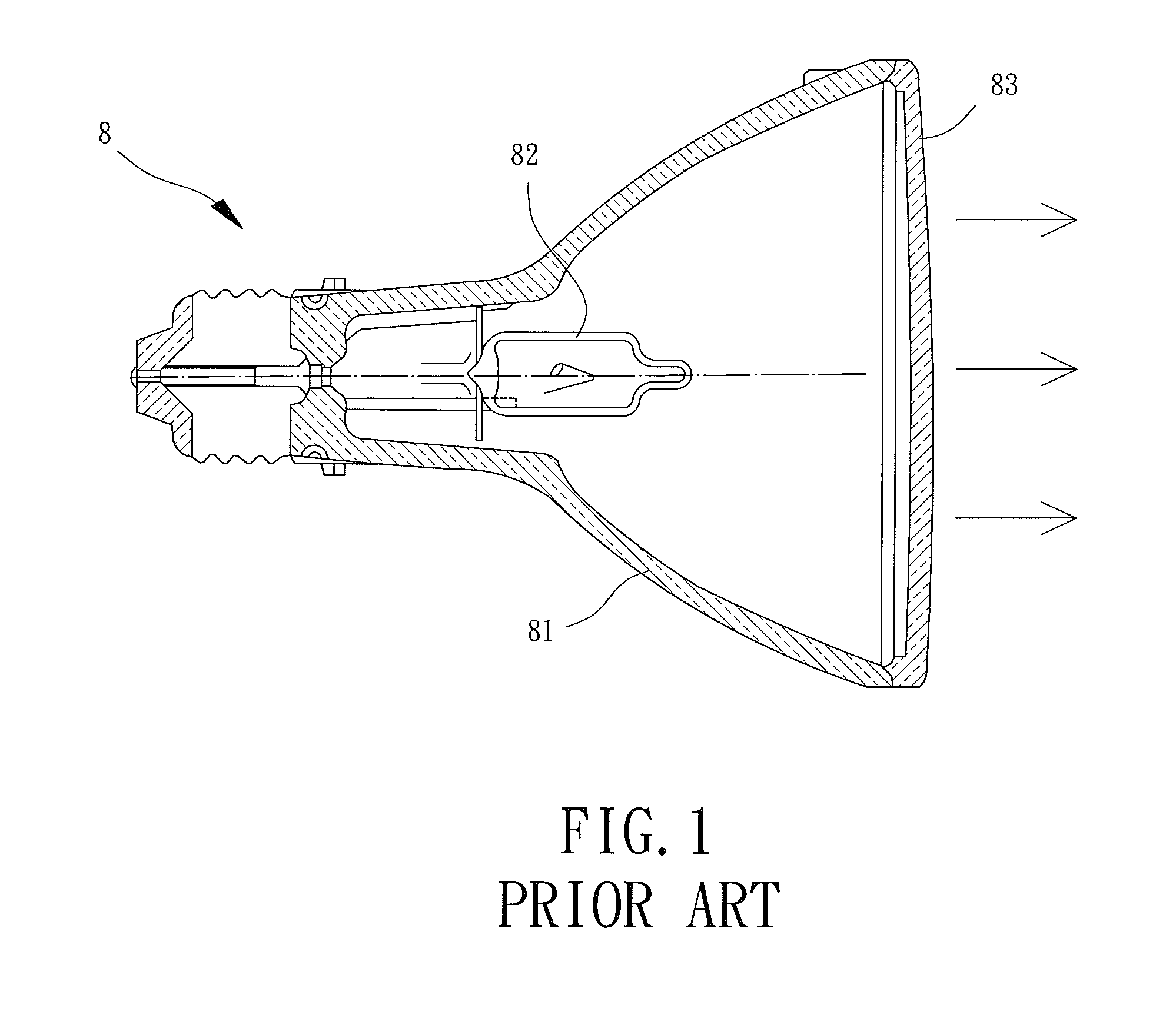
Figure 2 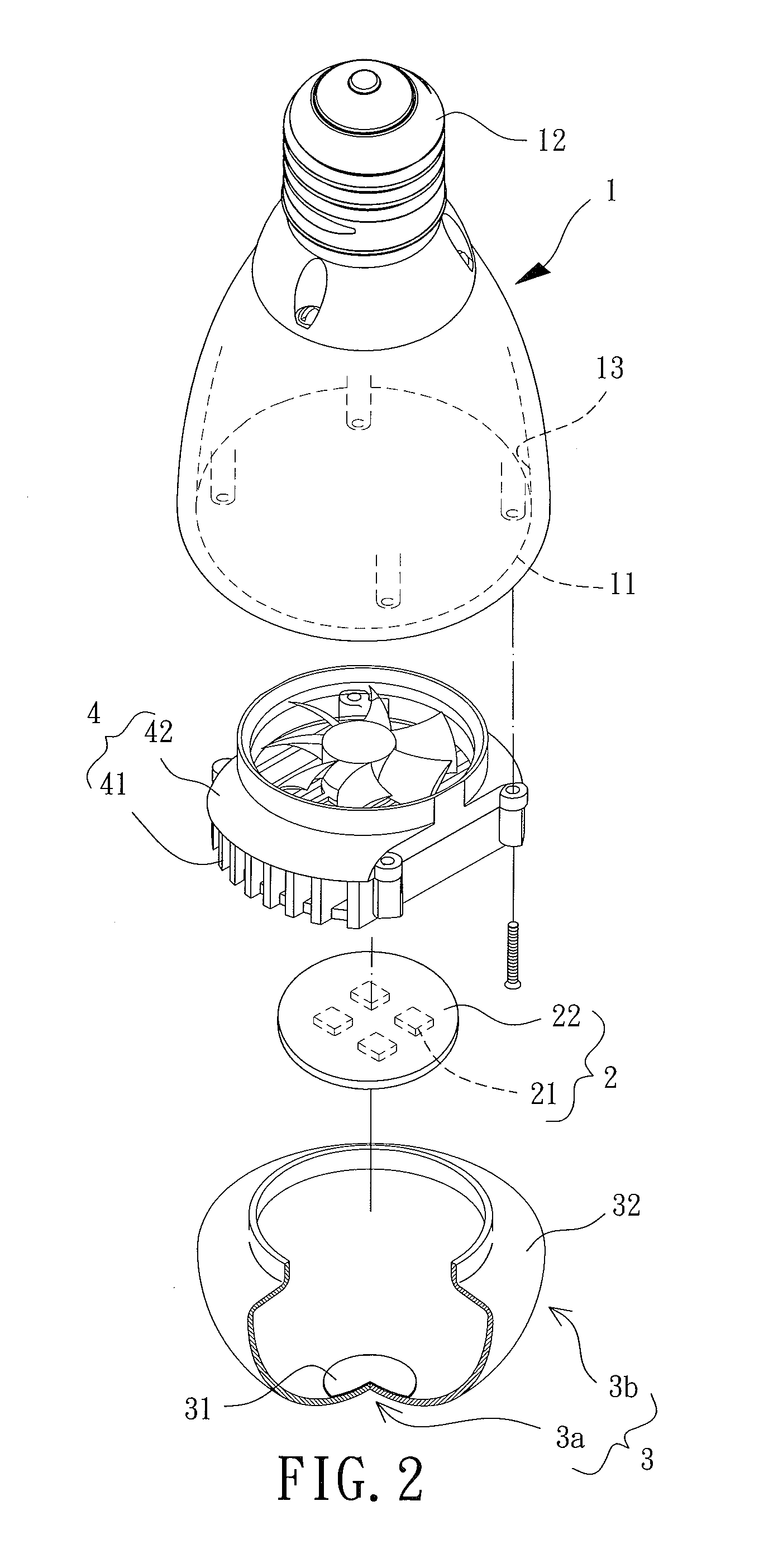
Figure 3
Abstract
Description
BACKGROUND OF THE INVENTION
[0001] 1. Field of the Invention
[0002] The present invention generally relates to a lamp with a wide-angle light emission and a bulb thereof and, more particularly, to a lamp emitting light over a wide angle using a diffusing reflector.
[0003] 2. Description of the Related Art
[0004] Referring to FIG. 1, a conventional lamp 8 of Taiwan Patent Publication No. 218249 entitled “electric reflector lamp” has a reflector 81 with a light emitter 82 inside. There is a bulb 83 made of a glass cap and mounted on an end of the reflector 81 for the light emitted by the light emitter 82 to be transmitted outside the reflector 81 via the bulb 83.
[0005] However, the bulb 83 of this conventional lamp 8 is unable to diffuse or reflect the light passing through the bulb 83, and, thus, most parts of the light emitted by the light emitter 82 can only be transmitted in a forward way shown as the arrows in FIG. 1 without radiating in other directions. Therefore, an angle illumination ...
Examples
Embodiment Construction
[0025]Referring to FIGS. 2 and 3a, a preferable embodiment of the present invention including a housing 1, a light emitting module 2 and a bulb 3 is shown. The housing 1 is utilized for the light emitting module 2 to engage with, the light emitting module 2 is received in the housing 1, and the bulb 3 is mounted to an end of the housing 1 for the light emitted by the light emitting module 2 to be transmitted outside the housing 1 via the bulb 3.
[0026]The housing 1 is a hollow casing, with a coupling portion 11 and a electrical connector 12 formed at two ends of the housing 1. The, coupling portion 11 is preferably an opening communicating with an inner chamber of the housing 1 for the light emitting module 2 to be received in the inner chamber via the coupling portion 11, and the electrical connector 12 is in a form able to electrically connect with an external electrical power as a power source of the present lamp.
[0027]The light emitting module 2 is arranged inside the housing 1 a...