
Protection circuit, battery control device, and battery pack
Patent Information
- Authority / Receiving Office
- US · United States
- Patent Type
- Patents(United States)
- Current Assignee / Owner
- Publication Date
- 2014-10-28
- Estimated Expiration
- Not applicable · inactive patent
Smart Images
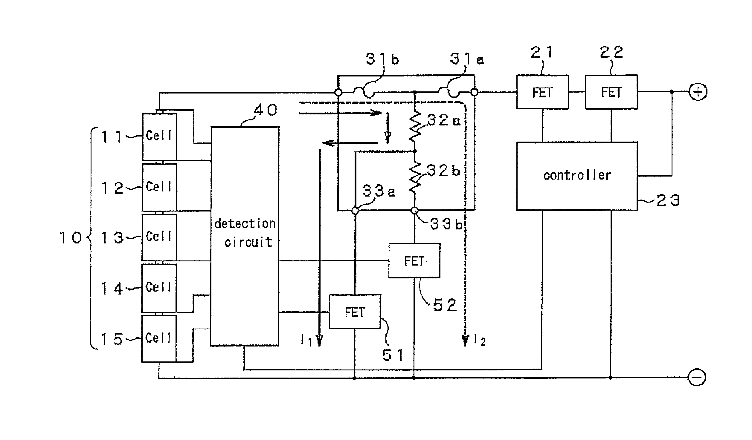
Figure 1 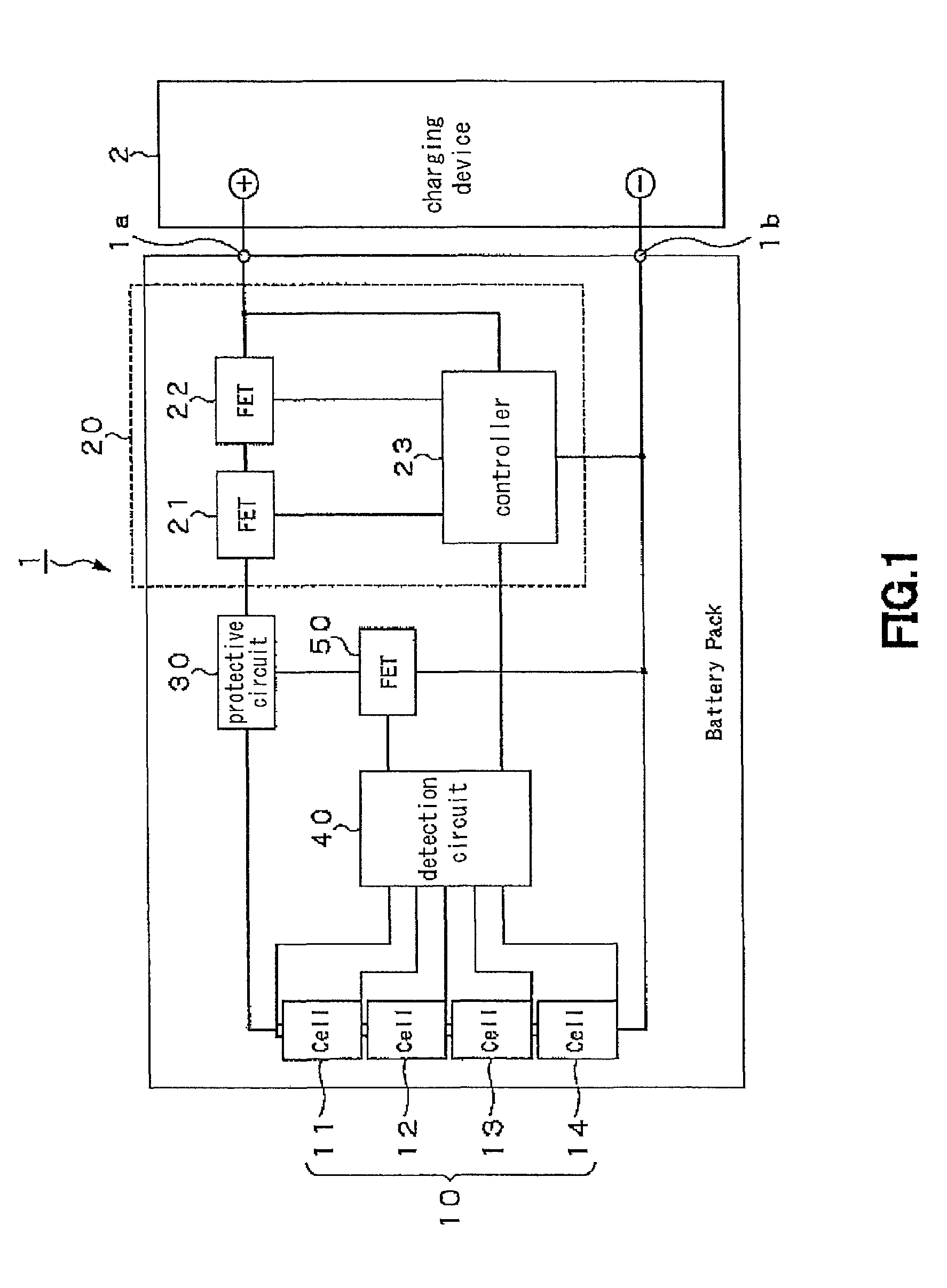
Figure 2 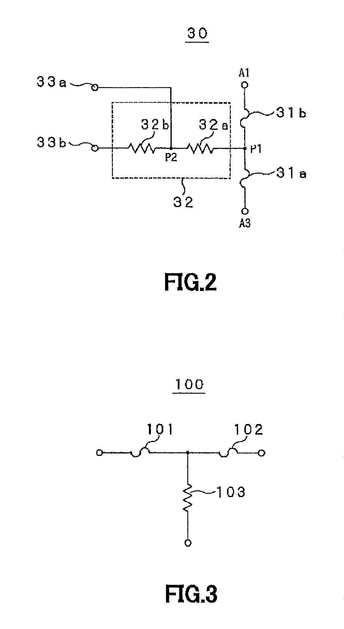
Figure 3
Abstract
Description
TECHNICAL FIELD
[0001] This invention relates to a protective circuit for protecting a battery unit composed by a plurality of chargeable / dischargeable battery cells and a charging / discharging control circuit. This invention also relates to the charging / discharging control device, with the protective circuit built therein, and to a battery pack.
[0002] The present application asserts priority rights based on JP Patent Application 2010-034436 filed in Japan on Feb. 19, 2010. The total contents of disclosure of the Patent Application of the senior filing date are to be incorporated by reference into the present Application.BACKGROUND ART
[0003] A protective circuit comprised of a heater and low melting metal arranged on a substrate has so far been used as a protective circuit that is able to prevent not only over-current but also over-voltage and that may be used to advantage for secondary batteries for use in e.g., mobile electronic equipment.
[0004] In the protective circuit that protects t...
Examples
Embodiment Construction
[0026]A preferred mode for carrying out the present invention will now be described with reference to the drawings. It should be noted that the present invention is not limited to the following mode such that a large variety of modifications may be made without departing from the purport of the invention.
[0027]
[0028]The protective circuit according to the present invention is a circuit that protects a battery unit composed by a plurality of chargeable / dischargeable battery cells and a charging / discharging control circuit. In use, the protective circuit is built into a battery pack 1 including a battery unit 10 made up of a sum total of four chargeable / dischargeable battery cells 11 to 14 shown for example in FIG. 1.
[0029]Specifically, the battery pack 1 includes the battery unit 10, a charging / discharging control circuit 20, a protective circuit 30, a detection circuit 40 and a current control element 50. The charging / discharging control circuit controls the charging / discharging of ...